make -j4
Boot the Raspberry Pi Pico you would like to act as a debugger with the
BOOTSEL button pressed and drag on
picoprobe.uf2.
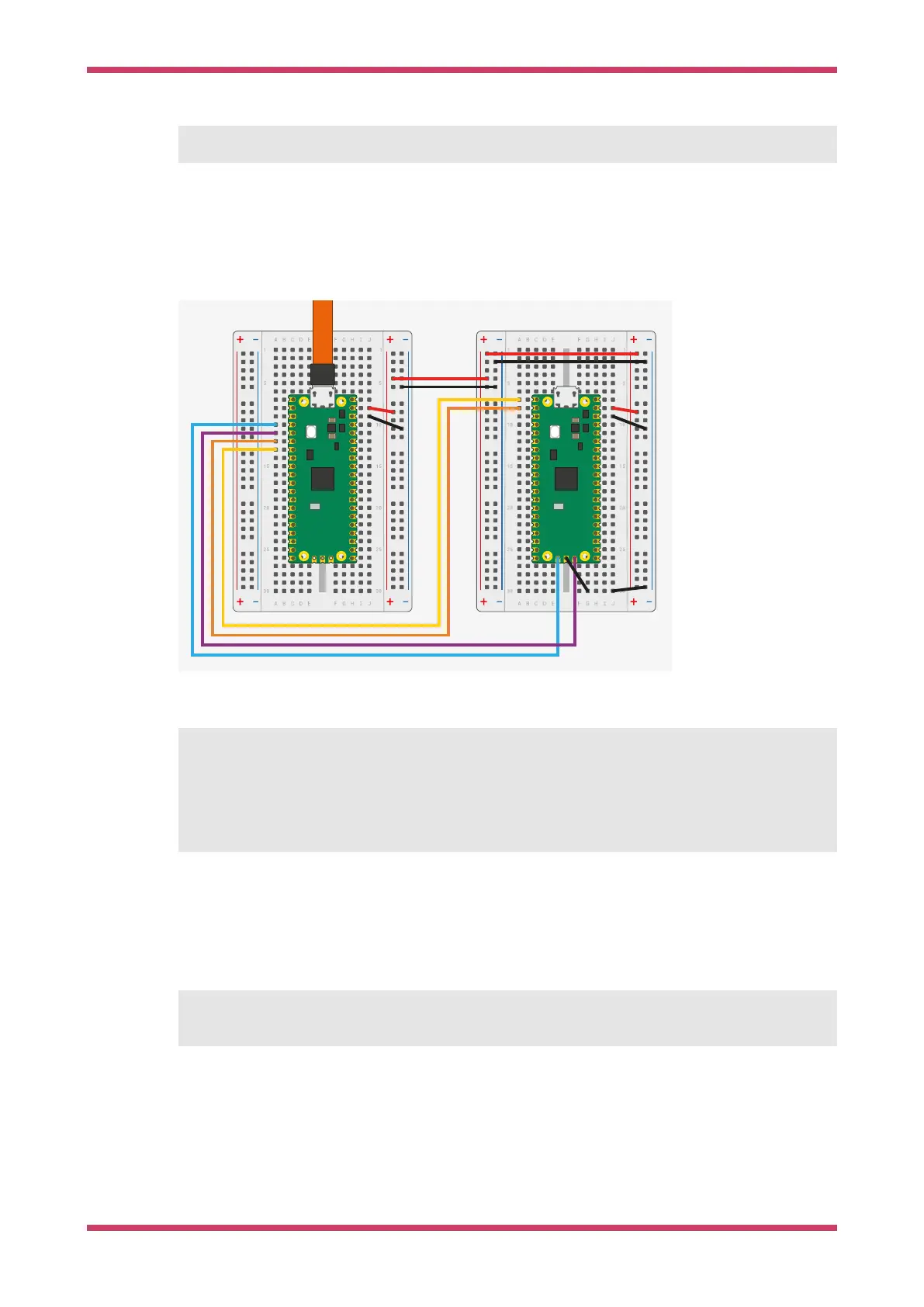
Picoprobe Wiring
Figure 36. Wiring
between Pico A (left)
and Pico B (right)
configuring Pico A as
a debugger. Note that
if Pico B is a USB Host
then you’d want to
hook VBUS up to VBUS
so it can provide 5V
instead of VSYS to
VSYS.
The wiring loom between the two Pico boards is shown in
Figure 36.
Pico A GND -> Pico B GND
Pico A GP2 -> Pico B SWCLK
Pico A GP3 -> Pico B SWDIO
Pico A GP4/UART1 TX -> Pico B GP1/UART0 RX
Pico A GP5/UART1 RX -> Pico B GP0/UART0 TX
The minimum set of connections for loading and running code via OpenOCD is GND, SWCLK and SWDIO. Connecting up
the UART wires will also let you communicate with the right-hand Pico’s UART serial port through the left-hand Pico’s
USB connection. You can also use just the UART wires to talk to any other UART serial device, like the boot console on a
Raspberry Pi.
Optionally, to power Pico A from Pico B you should also wire,
Pico A VSYS -> Pico B VSYS
Getting started with Raspberry Pi Pico
Picoprobe Wiring 61
 Loading...