- 39 - V-09 05/2014
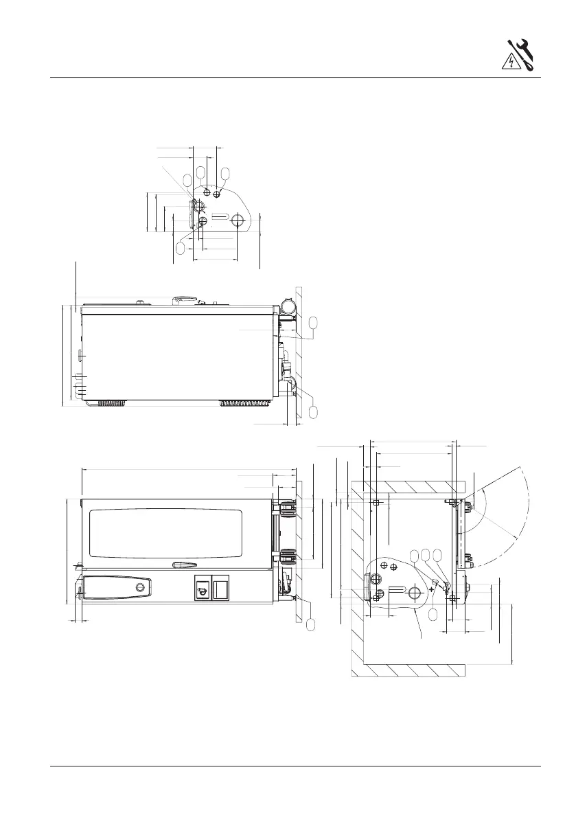
Schematic drawing 20x1/1 GN Gas
o
40
[
1-5/8
]
1782
[
70-1/8
]
190
[
7-1/2
]
55
[
2-1/8
]
877
[
34-1/2
]
790
[
31-1/8
]
137 [5-3/8]
71 [2-3/4]
67
[
2-5/8
]
798
[
31-3/8
]
27
[
1-1/8
]
752
[
29-5/8
]
158 [6-1/4]
370
[
14-5/8
]
152
[
6
]
1625 [6-3/8]
1025 [4]
629
[
24-3/4
]
52
[
2
]
715
[
28-1/8
]
34
[
1-3/8
]
120
565
[
22
]
577
[
22-3/4
]
52
[
2
]
500
[
19-5/8
]
50
[
2
]
55
[
2-1/8
]
2095 [8-1/4]
48
[
1-7/8
]
935 [3-5/8]
763
[
3
]
25
[
1
]
104
[
4
]
145
[
5-3/4
]
431
[
17
]
69
[
2-3/4
]
842
[
33-1/8
]
115
[
4-1/2
]
325
[
12-3/4
]
196
[
7-3/4
]
310
[
12-1/4
]
815 [3-1/4]
89
[
3-1/2
]
o
o
o
110
6
1
2
3
8
4
5
7
9
10
10
1 = Common water supply (cold water) (standard
as shipped)
2 = Water supply, cold water*
3 = Water supply, soft water*,
4 = Drain,
5 = Electrical connection,
6 = Earth bonding;
7 = Venting pipe 3"
8 = Gas supply 3/4”,
9 = Exhaust pipe steam
10 = Exhaust pipe hot air
Measures in mm (inch)
*= option after removal of T-connection
 Loading...