15
3. Connecting to the course computer
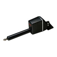
The linear drive unit has electrical connections for:
• the drive motor: two single-core cables: red and black
• the clutch: a two-core cable with red (+) and blue (-) cores
Follow these steps to connect the linear drive to the course computer:
1. Measure the distance of cable run from the drive unit to the course computer:
•use
Table 1-1
to identify the appropriate motor cable size
• use at least 1.5 mm
2
(16 AWG) copper cable for the clutch
2. Join these cables to the drive cables using appropriate electrical connectors or junction
boxes at the correct power rating.
3. Route the cables back to the course computer, taking into account the EMC installation
guidelines (see
page 9
).
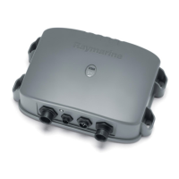
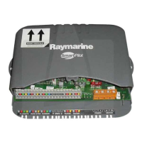
4. Connect the cables to the course computer (see
Figure 8
):
•
CLUTCH cable: red core to +ve, blue core to -ve
•
MOTOR cables: at this stage you can connect either motor cable to either terminal.
You will check these connections after installing the rest of the autopilot system.
WARNING
Moving parts
Keep clear of moving steering systems at all times. Protect moving parts
from access during normal use.
WARNING
Electrical safety
Make sure the power supply is switched OFF before you make any
electrical connections.

 Loading...
