Renesas RA Family UM-RA4E1, v1 User's Manual
R12UZ0142EE0100 Rev.0.1 Page
of 22
Oct.15.23
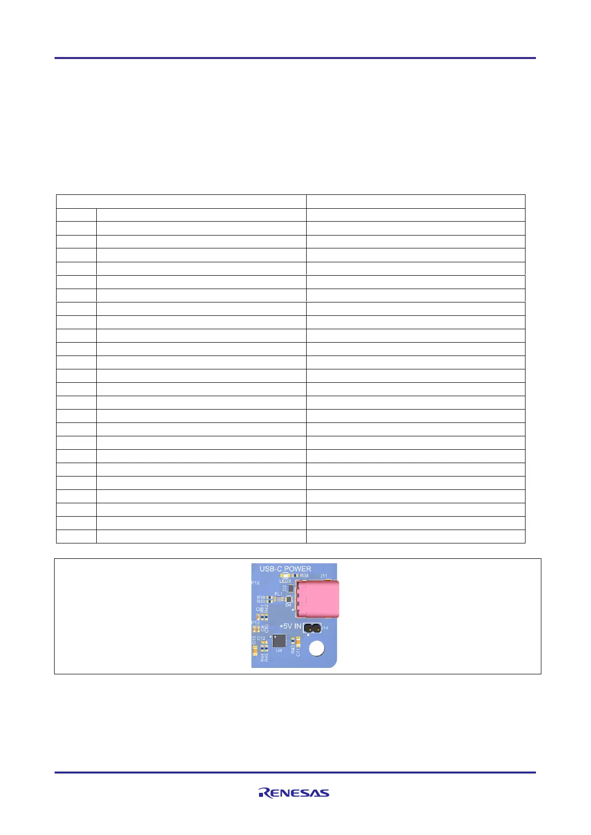
5.2.5 USB Full Speed
The USB C connection jack (J11) connects the Main MCU USB Full Speed interface to an external USB
interface, allowing communications for testing and use of the Main MCU firmware. This connection can be
configured as either a USB Device or a USB Host interface.
For a USB Device configuration, set Jumper J14 to pins 1-2, and configure the Main MCU firmware to use
the USB Full Speed ports in device mode. Power from an external USB Host on this connection can be used
to provide power to AIK-RA4E1.
Table 4. USB Full Speed Connector (J11)
Configuration Detection (CC1)
Configuration Detection (SBU1)
Configuration Detection (CC2)
Configuration Detection (SBU)
Figure 8. USB Full Speed Connector
5.2.6 PMOD 1
A 12-pin PMOD Type-2A connector is provided at PMOD 1. The Main MCU can act as the UART/SPI
master, and the connected module acts as an UART/SPI slave device. The Main MCU can be used also as
 Loading...


