Renesas RA Family EK-RA6M3 – Quick Start Guide
R20QS0011EU0102 Rev.1.02 Page 19 of 23
Jun.12.20
5.4 Setting Up Debug Connection between the EK-RA6M3 board and Host PC
To program the modified Quick St example project on to the EK-RA6M3 board, a debug connection is
necessary between the EK-RA6M3 board and host PC.
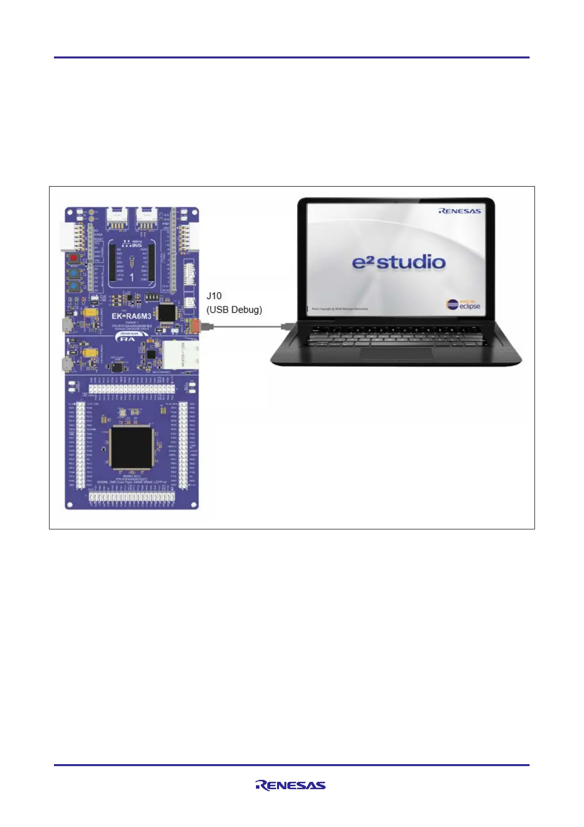
1. Disconnect the USB cable from micro-AB USB Full Speed port (J11) and connect it to micro-B USB
debug port (J10) of the EK-RA6M3 board.
Note: The EK-RA6M3 board supports 3 debugging modes. In this section and the following sections, default
debugging mode, Debug On-Board, is used. More information on debugging modes is available in
EK-RA6M3 user’s manual.
Figure 21. Connecting the EK-RA6M3 Board to the Host PC via USB Debug Port
2. Verify that the debug LED (LED5) stops blinking and lights up orange indicating that the J-Link drivers are
detected by the EK-RA6M3 board.
Note: The debug LED (LED5) continues to blink when J-Link drivers are not detected by the EK-RA6M3
board. In that case, make sure that the EK-RA6M3 board is connected to the host PC through the
micro-B USB debug port (J10) and that J-Link drivers are installed on the host PC by checking in the
Windows Device Manager (expand Universal Serial Bus controller, and locate J-Link driver)
 Loading...


