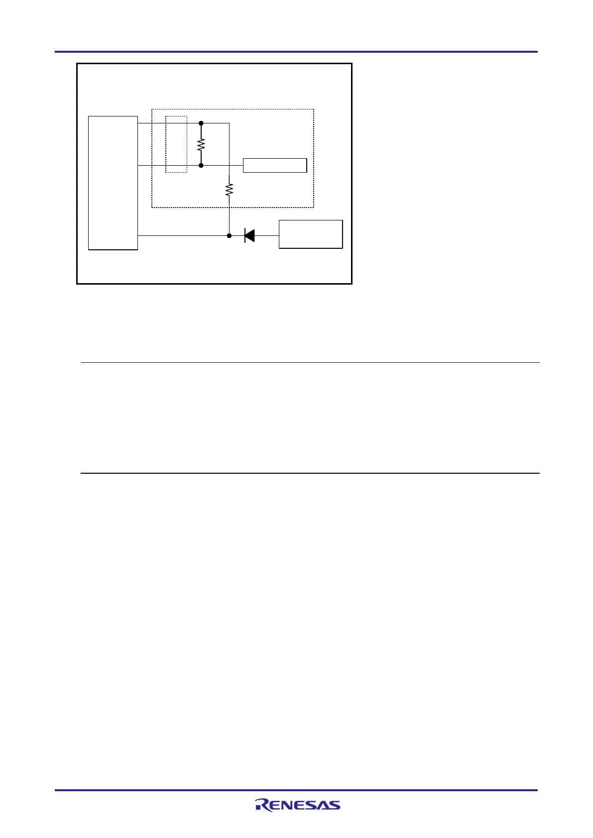
<Connection Example of RESET when the Target MCU is an RL78/I1C with the Battery
Backup Function in Use>
(Recommended Circuit)
470 to 510 W
1 kW
Reset circuit
6
10,13
RESET_IN
RESET_OUT
4
RSTPU
Note 1
14-pin
2.54-mm pitch
connector
MCU
RESET#
Note 2
Note 1: The emulator operates for flash programming by the programming software
whether this pin is connected or not.
Note 2: Connection is unnecessary when there is no reset circuit on the user system.
• Do not install capacitors, series resistors, or filters on signal lines; if attempted, correct communication may
not be established. There is an exception, however: capacitors can be inserted between VSS and
RESET_IN.
• The circuits and resistance values listed are recommended but not guaranteed. Determine the circuit design
and resistance values by taking into account the specifications of the target device and noise.
• Securely connect pins 2, 12, and 14 to GND of the user system. These pins are used for electrical
grounding as well as for monitoring of connection with the user system by the E1/E20/E2/E2 Lite. Securely
connect both pin 10 and pin 13.

 Loading...


