Service
Manual
C221 CD
Player
nd/ox
4
Functionaldescription
4.1 Seruo board
The following
functions are implemented
with the
circuits
on the
servo
board:
.
Control
of the supply
voltages
-
power
supply
.
Focus control-
photo
diodes of the signal
processor
.
Radial control
-
radial
processor
r
Motor
speed
control
-
demodulator
.
Drawer control
-
servo
processor
The
following connections
are located on the servo board:
.
Cable
(30
conductors)
to the
converter board
.
Cable
(14
conductors)
to the
player
mechanism
o
Stranded
wire
(4
conductors)to
the
drawer
limit switch
r
Stranded
wire
(3
conductors)to
the
drawer
motor
.
Stranded
wire
(4
conductors) to the disc motor
4.1.1 Control of
the supply
voltages
-
power
supply
The
power
supply
comprises the following components:
.
Transformer
(f1).
.
Two rectifier bridges
(D9,
D10, D'13, D14
and
D15...D18).
.
Five integrated voltage regulators
(S1...
54 and
lC 1).
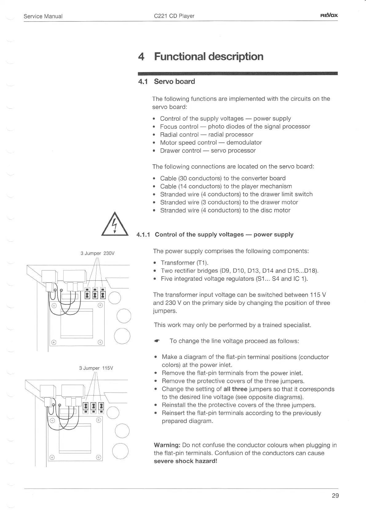
The transformer input
voltage
can be switched
between
1 15 V
and
230 V on the
primary
side by changing the
position
of
three
jumpers.
This work may only be
performed
by a
trained
specialist.
(.r
To change the
line
voltage
proceed
as follows:
.
Make
a
diagram of the flat-pin
terminal
positions
(conductor
colors) at
the
power
inlet.
.
Remove
the flat-pin
terminals
from the
power
inlet.
.
Remove
the
protective
covers
of
the three
jumpers.
.
Change
the setting of all three
jumpers
so that it
corresponds
to the desired line voltage
(see
opposite diagrams).
o
Reinstall the the
protective
covers of the three
jumpers.
.
Reinsert the
flat-pin terminals
according to the
previously
prepared
diagram.
Warning:
Do not
confuse
the
conductor colours when
plugging
in
the flat-pin terminals. Confusion of the conductors can cause
severe shock
hazardl
3 Jumper
3 Jumper
115V
29
 Loading...