REVOX
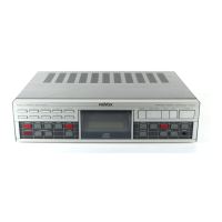
C221
CD
Player
Service
Manual
4.2 Converter board
The converter board
contains the following
circuits or
functions:
e
Microprocessor
(control
microprocessor)
.
Serial system
bus
(DlN
connectors)
-
optocoupler
.
Parallel
remote connection
-
optocoupler
.
Digital/analog converter
-
two
bitstream converters
o
Reset circuit
.
Modulation start
monitoring
(mode
detection)
4.2.1 Microprocessor
Resistors
R57
and
R58
(both
O ohm) can be soldered
into two
different
positions:
.
The
position
of
resistor R57
determines
whether a micro-
processor
with an
external mask
or an external
EPROM is to
be used.
.
The
position
of
resistor R58
determines
whether a 16 k or 32
k
EPROM
(1C10)
is insefied.
The keypad is connected
via lC8.
The
serial bus of
lC.l
is
used as the
system bus and consists
of a
transmitter
fl-X)
and receiver
(RX).
The interrupt input lNTO is used for the LOAD
key.
The second,
internal serial
bus from
poft
1 is used for the display
and
comprises data, clock and
enable
(SDATA,
SCLCK,
DTGENABLE).
lC2
(UART)supports
the
communication between the
microprocessor
and
the
servo
processor
on
the
servo board.
The
UART communicates
with
the microprocessor in
parallel
mode, and with the servo
processor
in
serial mode.
The PSON and RES
pP
signals
are inverted and
supplied
to the
servo board.
PSON activates
the
power
supply; RES
pP
initializes
the servo
processor
lC3
on the servo
board.
4.2.2 Serial system bus
-
optocoupler
The
serial system bus
is connected
via two DIN sockets and
supports
the
communication
with
a PC via a
serial
interface.
The inputs and outputs are electrically isolated via
optocouplers.
The serial bus, consisting of a
receive
and a transmit line operates
with 9600 baud and
a level
of 5 V.
32
 Loading...