Do you have a question about the Rheem 871018 and is the answer not in the manual?
| Brand | Rheem |
|---|---|
| Model | 871018 |
| Category | Water Heater |
| Language | English |
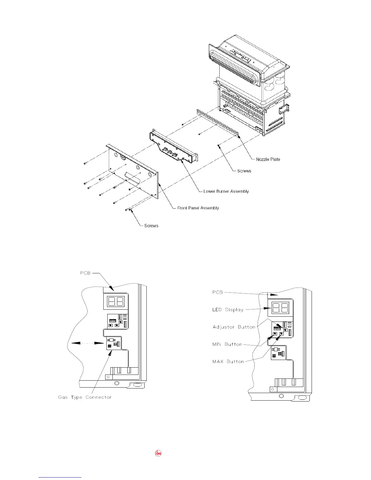
Step-by-step guide to adjusting the water heater's preset temperature using DIP switches and buttons.
Outlines the recommended procedure for diagnosing and rectifying faults on the water heater.
Visual flow diagram guiding users through the fault diagnosis process.
Lists error codes, their causes, and diagnostic steps for troubleshooting.
Provides a table of test points, wiring, normal conditions, and items under test.
Provides flow charts for troubleshooting specific operational issues and error codes.
Details the fault finding process for ignition and temperature control issues.
Outlines flow charts for post-purge shutdown and other operational faults.
Step-by-step guide to displaying maintenance information via the water heater or remote controller.
Procedure for clearing the error code history after repairs.
Instructions on how to reset specific error codes, particularly Error Code 99.
A flowchart guiding the user through a fault diagnosis sequence based on LED display.
Guide for diagnosing power supply and transformer related issues.
Covers troubleshooting for overheating, communication failures, and fan circuit issues.
Focuses on ignition and temperature control faults, including thermistor and fan speed issues.
Illustrates tests for power supply, transformer, and power filter checks.
Deals with flame failure, abnormal combustion, and purge failures.
Focuses on water flow servo malfunctions and bypass solenoid issues.
Addresses outlet water temperature issues and solar bypass valve/comparator checks.
Focuses on fan current detection circuit failures.
Covers issues related to in-series gas boosting and flow sensor checks.
Addresses solar bypass valve/comparator fitting and water flow sensor issues.
Details procedures for preheated water issues and solar bypass valve functionality.
Covers tests for water flow sensor and flow sensor turbine.