19
ELEVATED SINGLE PIPE ALTERNATE TEE TERMINATION
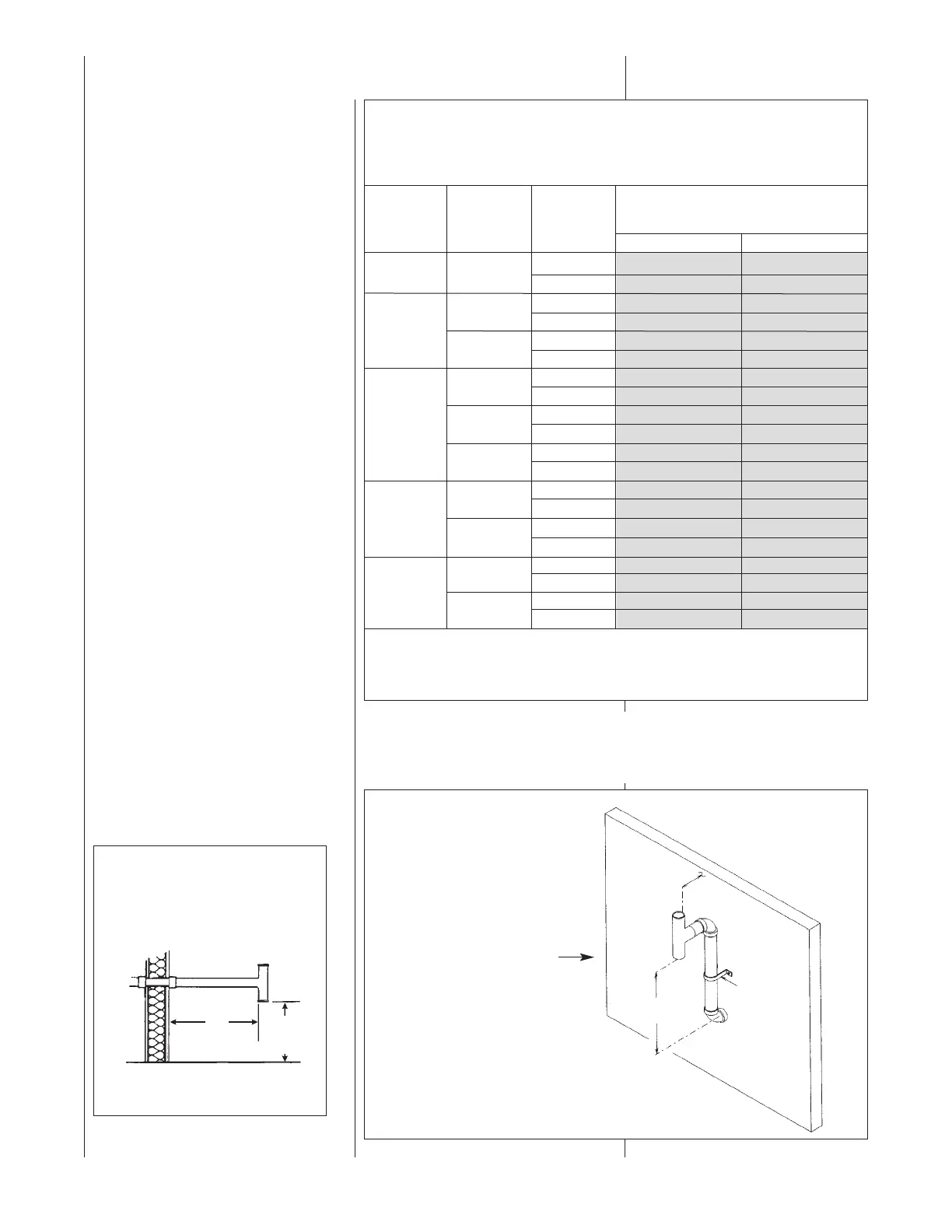
See Figure 16. The tee termination may be elevated up to 24 inches above the
wall penetration if required for anticipated snow levels. Use 2 medium-radius, 2-in.
PVC elbows and 2-in. PVC pipe, attaching the tee so it is 12 inches from the wall.
NON-DIRECT VENT
INSTALLATION
GUIDELINES
IMPORTANT: Failure to correctly
follow all venting guidelines may
result in erratic furnace operation,
freeze-up of combustion air or
exhaust air piping or sooting of the
furnace.
All exhaust piping must be installed in
compliance with Part 7, “Venting of
Equipment,” of the latest edition of the
National Fuel Gas Code NPFA54/
ANSI Z223.1-, local codes or
ordinances and these instructions.
1. Vertical piping is preferred.
2. All horizontal piping must slope
upward a minimum of
1
⁄4 inch
per foot of run so that
condensate drains toward the
furnace.
3. All horizontal runs must be
supported at least every 4 feet.
No sags or dips are permitted.
4. IMPORTANT: Do not common
vent with any other appliance. Do
not install in the same chase or
chimney with a metal or high
temperature plastic pipe from
another gas or fuel-burning
appliance unless the required
minimum clearances to
combustibles are maintained
between the PVC pipe and other
pipes.
5. All vent runs through
unconditioned spaces where
below-freezing temperatures are
expected should be insulated
with 1-in. thick, medium-density,
foil-faced fiberglass. An
equivalent “arm-a-flex” or
FIGURE 15
TEE TERMINAL – FOR STANDARD
HORIZONTAL SINGLE PIPE
INSTALLATION
FIGURE 16
ALTERNATE HORIZONTAL TERMINATION
FOR NON-DIRECT VENT
INSTALLATIONS
NOT APPLICABLE TO
GTC-07 MODELS
GTC-09 MODELS
GTC-10 MODELS
12"
FROM
24"
MAX.
PIPE
SUPPORT
STRAP
OUTSIDE
WALL
VENT
12"
12" MIN. ABOVE
GRADE OR
SNOW LEVEL
I198
NUMBERS OF ELBOWS
45° OR 90°
Medium / Long Radius ONLY
1-2 3-4
2”
Standard 60 50
45,000
Alternate 50 40
2”
Standard 50 40
Alternate 40 30
60,000
3”
Standard 60 50
Alternate 50 40
2”
Standard 25 N/A
GRC Only
Alternate N/A N/A
75,000
3”
Standard 50 40
GRC Only
Alternate 40 30
3”
Standard 50 40
GTC Only
Alternate N/A N/A
3”
Standard 50 50
90,000
GRC Only
Alternate 50 40
3”
Standard 50 40
GTC Only
Alternate N/A N/A
3”
Standard 60 50
105,000
GRC Only
Alternate 50 40
3”
Standard 50 40
GTC Only
Alternate N/A N/A
NOTES:
1. *N.A. - NOT APPLICABLE.
2. MAXIMUM OF 6 - 90 DEGREE ELBOWS MAY BE USED. DO NOT COUNT ELBOWS REQUIRED FOR
ALTERNATE TERMINATION. USE ONLY MEDIUM OR LONG SWEEP ELBOWS.
3. A 45° DEGREE ELBOW IS CONSIDERED ONE ELBOW.
FURNACE
INPUT
VENT PIPE INSTALLATION
PIPE
SIZE
TERMINATION
TABLE 1
FOR NON-DIRECT VENT APPLICATIONS - AIR FOR COMBUSTION
PROVIDED FROM INDOORS
MAXIMUM ALLOWABLE LENGTH IN FEET OF EACH EXHAUST PIPE AND INTAKE PIPE
 Loading...