37
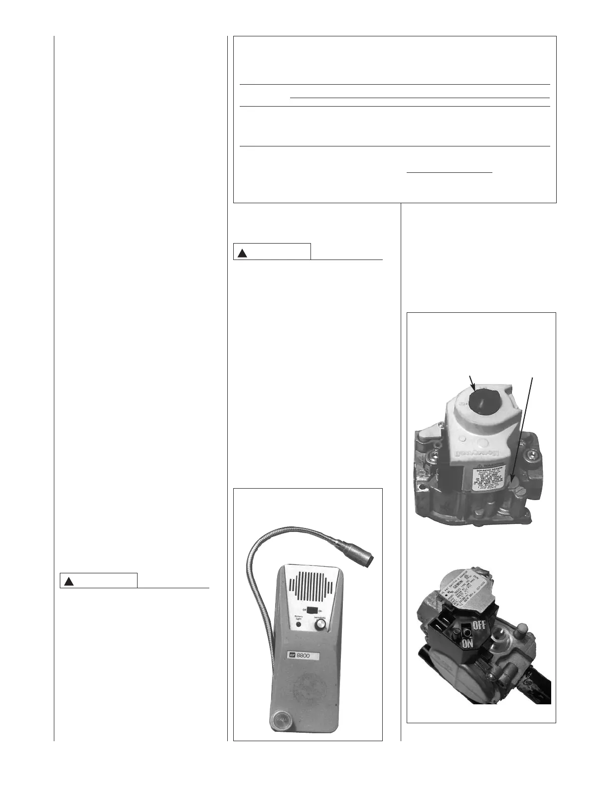
FIGURE 39
TYPICAL GAS VALVES
HONEYWELL
PRESSURE
CONTROL REGULATOR
KNOB ADJUSTMENT
however 6⬙ to 7⬙ is recommended.
The minimum supply pressure is 11⬙
w.c. for LP gas.
NEVER PURGE A GAS LINE INTO
THE COMBUSTION CHAMBER.
NEVER USE MATCHES, FLAME OR
ANY IGNITION SOURCE FOR
CHECKING LEAKAGE. FAILURE
TO ADHERE TO THIS WARNING
CAN CAUSE A FIRE OR
EXPLOSION RESULTING IN
PROPERTY DAMAGE, PERSONAL
INJURY OR DEATH.
To check for gas leakage, use an
approved chloride-free soap and
water solution, an electronic com-
bustible gas detector (see Figure 38),
or other approved method.
GAS VALVE
This furnace has a 24-volt operated
valve. It has ports for measuring
supply pressure and manifold
pressure. The valve body contains a
Install a ground joint union inside
the cabinet to easily remove the
control valve assembly. Install a
manual shut-off valve in the gas
line outside the furnace casing.
The T-valve should be readily
accessible to turn the gas supply on
or off. Install a drip leg in the gas
supply line as close to the furnace as
possible. Always use a pipe
compound resistant to the action of
liquefied petroleum gases on all
threaded connections.
IMPORTANT: When making gas pipe
connections, use a back-up wrench to
prevent any twisting of the control
assembly and gas valve.
Any strains on the gas valve can
change the position of the gas orifices
in the burners. This can cause erratic
furnace operation.
IMPORTANT: Do not run a flexible
gas connector inside the unit. If local
codes allow the use of a flexible gas
appliance connector, always use a
new listed connector. Do not use a
connector which has previously
serviced another gas appliance.
Massachusetts law requires that all
flexibile connectors be less than 36ⴖ.
The gas pipe gasket in the cabinet
does not seal around a flexi-ble gas
connector. It is important to have all
openings in the cabinet burner
compartment sealed for proper
furnace operation.
IMPORTANT: ENSURE that the
furnace gas control valve not be
subjected to high gas line supply
pressures.
DISCONNECT the furnace and its
individual shut-off valve from the gas
supply piping during any pressure
testing that exceeds 1/2 PSIG.
(3.48 kPa).
GAS PRESSURE
Natural gas supply pressure should
be 5" to 10.5" w.c. LP gas supply
pressure should be 11" to 13" w.c.
This pressure must be maintained
with all other gas-fired appliances
in operation.
ELEVATIONS ABOVE 2000 FT
REQUIRE THAT THE FURNACE
INPUT RATING BE ADJUSTED
AND THAT THE SIZE OF THE
BURNER ORIFICES BE RE-
CALCULATED BASED ON
ELEVATION AND GAS HEATING
VALUE. THE BURNER ORIFICES
MAY (OR MAY NOT) NEED TO BE
CHANGED. SEE THE SECTION
TITLED “HIGH ALTITUDE
INSTALLATIONS” OF THIS BOOK
FOR INSTRUCTIONS.
The minimum supply pressure to the
gas valve for proper furnace input
adjustments is 5⬙ w.c. for natural gas,
!
WARNING
FIGURE 38
ELECTRONIC COMBUSTIBLE GAS
DETECTOR
TABLE 3
NATURAL GAS PIPE CAPACITY TABLE (CU. FT./HR.)
Capacity of gas pipe of different diameters and lengths in cu. ft. per hr. with pressure drop of 0.3 in. and specific
gravity of 0.60 (natural gas).
Nominal Length of Pipe, Feet
Iron Pipe
Size, Inches 10 20 30 40 50 60 70 80
1/2 132 92 73 63 56 50 46 43
3/4 278 190 152 130 115 105 96 90
1 520 350 285 245 215 195 180 170
1-1/4 1,050 730 590 500 440 400 370 350
1-1/2 1,600 1,100 890 760 670 610 560 530
After the length of pipe has been determined, select the pipe size which will provide the minimum cubic feet per hour
required for the gas input rating of the furnace. By formula:
Gas Input of Furnace (BTU/HR)
Cu. Ft. Per Hr. Required =
Heating Value of Gas (BTU/FT
3
)
The gas input of the furnace is marked on the furnace rating plate. The heating value of the gas (BTU/FT3) may be
determined by consulting the local natural gas utility or the LP gas supplier.
pressure regulator to maintain proper
manifold pressure.
A manual control is on the valve
body. It can be set to only the “ON”
or “OFF” positions. The gas valve is
a slow-opening valve. See Figure 39.
When energized, it takes 6 to 8
seconds to fully open.
WHITE RODGERS
!
CAUTION
 Loading...