COMBUSTION ADJUSTMENT
THE FOLLOWING BURNER
ADJUSTMENTS MUST BE MADE
AFTER 10 TO 15 MINUTES OF
OPERATION.
8. Set the draft. Remove the heat
shield and then remove the metal
plug in the burner mounting plate.
Check the draft reading over the
fire with a draft gage through the
5/16" hole located in the burner
plate. See the draft gauge section
in this manual for more
information. Adjust the barometric
damper to give the overfire draft
recommended by the manufacturer.
If no such recommendations are
available, set the overfire draft to
assure a negative pressure within
the combustion chamber (usually a
negative 0.01 to 0.02 inches water
column).
Replace the hole plug in the
burner mounting plate after these
tests have been made.
9. Check the smoke readings. After
the burner has been operating 10
minutes, make a smoke measure-
ment in the flue following the
smoke tester instructions. See the
smoke pump section in this
manual for more information. Oily
or yellow smoke spots on the filter
paper are usually a sign of un-
burned fuel, indicating very poor
combustion (and likely high emis-
sions of carbon monoxide and
unburned hydrocarbons). This
condition can sometimes be
caused by too much air, or other
factors. If this condition cannot be
corrected, major correction or
even burner replacement may be
necessary. Adjust the air shutter
and air band for a 0 to a 1 smoke
number (a trace).
10. Check the CO
2
with the Fyrite
analyzer. See Fyrite Gas Analyzer
section for methods and
procedures. Adjust the air setting
to reduce the CO
2
reading by
between 1% and 2%. Lock the air
adjustment and repeat all draft,
CO
2
, and smoke measurements to
make sure the setting has not
shifted.
COMBUSTION DIAGNOSIS
11. Check performance. A well-
matched and well-tuned burner
should be capable of operation at
a CO
2
level between 10% and
12%.
FINAL CHECKS
12. Measure the flue temperature.
See the stack thermometer
section in this manual for more
information. Operating the unit at
an excessive firing rate generates
pollutant emissions. Check for
prompt pump cutoff by observing
the flame or by checking for
smoke at shutdown. If poor cutoff
is observed, make sure all air is
purged from the pump and nozzle
line. If poor cutoff continues check
for proper cutoff pressure.
15. Check Controls. Check the
settings of all operating controls
before leaving the installation and
verify that they are in working
order.
16. Check for proper temperature rise
of the supply air. See the air
supply temperature section in this
manual for details.
17. Annual Cleanup. An overall burner
checkup and cleanup is
recommended annually. See the
annual cleanup section in this
manual for more information.
13
more heat than the heat
exchanger can utilize and results
in unnecessary heat loss up the
chimney. Other causes of
excessive heat loss are badly
sooted heat-exchanger surfaces
and excessive draft. The tempera-
ture of the flue gas provides an
indication of these heat losses.
Measure the net flue temperature
by subtracting the room air tem-
perature from the thermometer
reading. Excessive flue loss is
indicated if the net flue
temperature during steady
operation exceeds 600° F.
13. Check Ignition. Check the
operation over repeated cycles to
insure prompt ignition on starting.
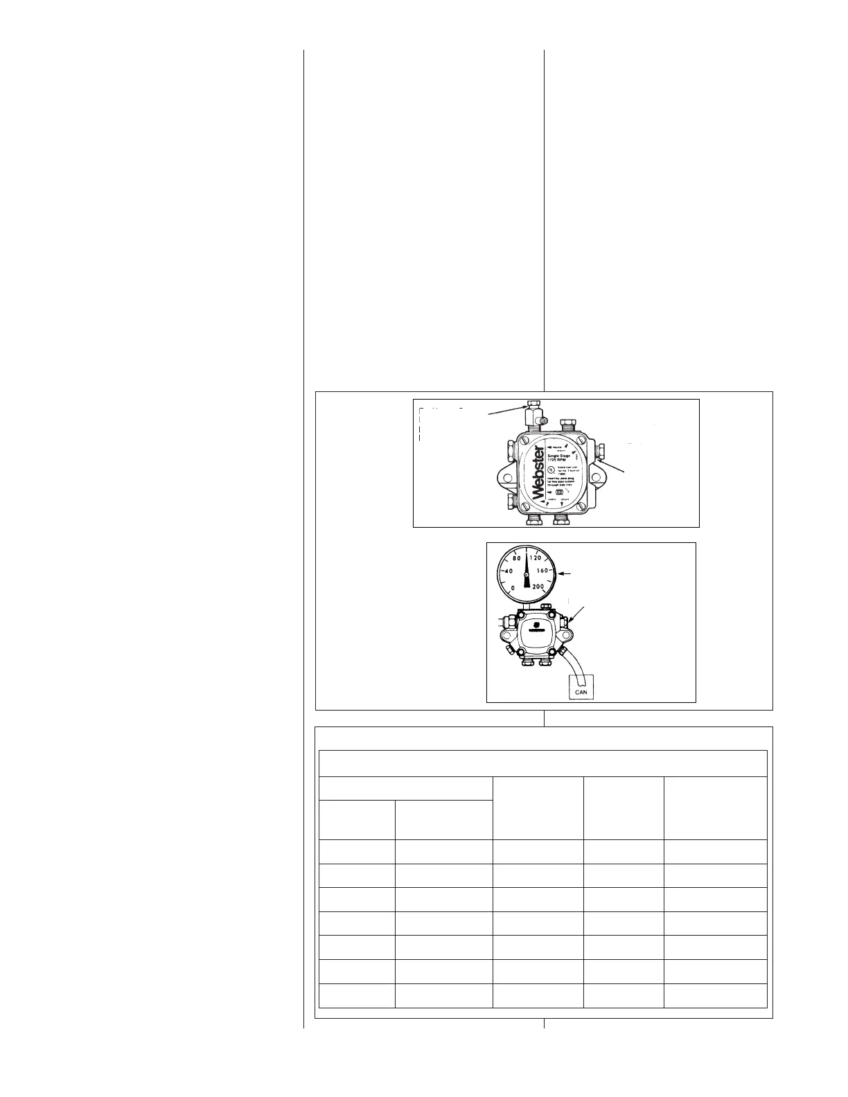
14. Check pump cutoff. See pump
section for the procedure for
checking cut off pressure. Slow
pump cutoff at the end of a firing
cycle can cause smoke and other
FIGURE 13
FIGURE 14
Table 11
FACTORY AIR ADJUSTMENT SETTINGS
BURNER
AIR SHUTTER
SETTING
AIR BAND
SETTING
OIL FURNACE
MODEL
BECKETT
MODEL
AFG AF42JYPWHS 10 BLANK -056
AFG AF42JYPWHS 10 BLANK -067
AFG AF42XNPWHS 10 2 -084
AFG AF42XNPWHS 10 2 -095
AFG
AFG
AFG
AF42XNPWHS
AF42JZPWHS
AF42JZPWHS
10
7
7
2
4
4
-112
-130
-150
BECKETT
DESIGNATION
For Use as Gage
Port. Remove vent
plug to install 1/49
pipe threaded gage.
To Adjust Pressure:
Insert standard
screwdriver. Turn
counterclockwise to
below pressure
desired. Turn
clockwise to set to
desired pressure.
GAGE PORT
PRESSURE
PRESSURE ADJUSTMENT
 Loading...