Install a single wall, vent connector
from flue outlet to chimney, sloping flue
pipe continuously upward (at least 1/4
inch per foot) toward chimney. The
vent connector should be the same
diameter as the flue collar of the
furnace for the entire length of run and
should not exceed 10 feet in length.
Avoid sharp turns that would create
resistance to the flow of flue gasses.
Vent connector should not extend
beyond the inside wall of the chimney
and must be firmly cemented to
masonry.
IMPORTANT: This furnace is agency
approved by UL, ULC and CSA for use
with the Tjernlund SS1-R sidewall vent
system when installed in accordance
with the installation instructions for the
SS1-R provided by Tjernlund. The
maximum vent length is 10 feet with 3
elbows when venting with the SS1-R.
This is the only option given for side
wall venting. It should be noted that
common venting with another
appliance is not an option when using
the Tjernlund SS1-R. The use of any
other type of power vent system is not
approved or recommended by the
manufacturer.
No other appliances or heating
equipment should be connected to the
vent connector servicing the furnace.
Bolt, screw and/or support joints to
avoid sag. Fasten the single-wall vent
connector to the outlet collar of the
furnace with at least two sheet metal
plumb. Tilting causes erratic damper
operation. Installation of a barometric
damper must be in accordance with the
Installation and Operation Instructions
provided with the damper.
The following standards and codes will
help to make the installation. Current
editions of these standards can be
obtained from:
American National Standards Institute,
1430 Broadway, New York, NY 10018
OIL BURNER / PRIMARY
CONTROL
Oil burner and primary control are
mounted to the furnace as a complete
assembly. Standard equipment
consists of the oil burner, primary
control and flame sensor mounted as a
single assembly to the furnace. The
heat/cool relay is mounted to the unit’s
main junction box and the flame sensor
(cadmium sulfide cell) is enclosed in
the burner housing above the blower
wheel.
The standard oil burner is equipped
with a single stage fuel pump. This
single stage fuel pump may be used in
either a one or two pipe system. If a
two pipe system is required (burner is
screws. Refer to Figure 1 for distances
to combustible materials.
DEVICES ATTACHED TO THE FLUE
OR VENT FOR THE PURPOSE OF
REDUCING HEAT LOSS UP THE
CHIMNEY HAVE NOT BEEN TESTED
AND HAVE NOT BEEN INCLUDED IN
THE DESIGN CERTIFICATION OF
THIS FURNACE. WE, THE
MANUFACTURER, CANNOT AND
WILL NOT BE RESPONSIBLE FOR
INJURY OR DAMAGE CAUSED BY
THE USE OF SUCH UNTESTED
AND/OR UNCERTIFIED DEVICES,
ACCESSORIES OR COMPONENTS.
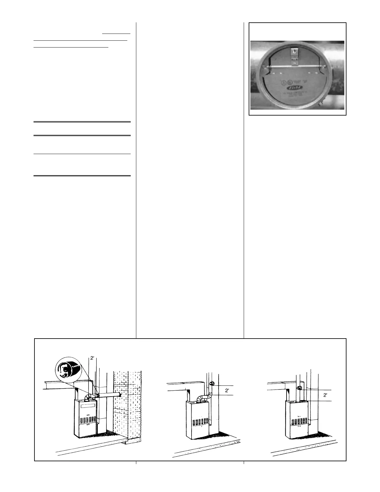
BAROMETRIC DRAFT
CONTROL
The barometric damper (see figure 7) is
a control installed in the flue pipe to
regulate the draft in the furnace. If the
draft increases in the chimney, the
damper opens to maintain the preset
draft in the furnace. Should the draft
decrease in the chimney, the damper
will close to maintain the preset draft of
the oil furnace. A barometric damper is
supplied with each furnace and must be
installed by the following the
instructions supplied by the
manufacturer. The barometric damper
control should be installed between the
flue outlet of the furnace and the
chimney (see figure 8). The barometric
damper control should be set for proper
draft on start up after the furnace has
been operating for 10 to 15 minutes.
See Oil Burner Adjustment Procedure
Section for proper draft settings.
On start up, the furnace must be set
for field conditions with a
combustion kit for proper operation.
Note: Always use a seperate
barometric damper for each oil-fired
appliance. Install the barometric
damper with its hinge level and the face
8
TABLE 1. Metal Thickness for Galvanized Steel Pipe
Connectors
Diameter of Galvanized Minimum
Connector Sheet Thickness
(in.) (mm) Gauge No. (in.) (mm)
< 6 < 152 26 0.019 0.48
≥ 6 to ≤ 10 ≥ 152 to ≤ 254 24 0.024 0.61
> 10 to ≤ 16 > 254 to ≤ 406 22 0.029 0.74
>16 > 406 16 0.056 1.42
Figure 8
Recommended Barometric Damper Locations
Figure 7
Barometric Damper
 Loading...