9
5. WATER CONNECTIONS
CAUTION: The heater inlet and outlet are NOT
interchangeable. They must be connected as instructed
below.
A
WARNING: Improper installation of any type of
automatic chemical feeders can result in serious damage
to, or premature failure of, the heater and such damage
will not be covered under warranty. Install a check valve
and/or a Hartford loop AFTER the heater and BEFORE
any chlorinating devices. Install any automatic chemical
feeders AFTER the heater.
1. Connect the heater in the return water line between
the filter and the pool/spa. See plumbing diagrams
on page 38 (without bypass) and page 39 (with
bypass).
2. Connect the filter outlet to the fitting marked INLET at
the bottom front of the unit.
3. Connect the fitting marked OUTLET to the return
piping to the pool/spa. Unit inlet/outlet connection
fittings are 2-inch PVC unions on models 4550-8550.
Water connections from the unit to the main return line can
be PVC pipe or exible pipe approved for the purpose and,
in either case, should be at least equal in size to the main
pool/spa circulation piping.
• Water flow to the unit will exceed 40 GPM (151 LPM)
for 4550 models or 50 GPM (189 LPM) for 5550-
8550 models. See Figure 64 for bypass instructions.
• To protect (completely bypass) the unit from any
harmful chemical treatments (i.e. Acid wash, back-
to-back super chlorinators, stain treatments, etc.); or
to be able to isolate the unit for service/repair or
freeze preparation and still allow pool/spa circulation
to continue.
In Heat/Cool models, a bypass assembly is included.
Please refer to the plumbing on page 39, for further
instruction.
Please note that some municipalities do not allow the use
of a shutoff valve on the efuent/outlet side of any heating
equipment, especially when there is one on the inlet side.
These entities typically instead allow a PVC tee and spring
check valve on the efuent/outlet side. This is allowed
by Raypak and can also double as your protection from
chemical feeders and chlorinators that are downstream of
the unit.
4. Operate the pump and check the system for leaks.
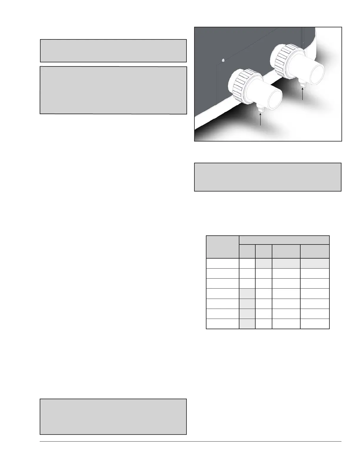
5. Drain plugs are located on each union fitting as shown
in Figure 6 for draining the system during winterizing.
NOTE: While it is possible to mount the upper union
with the drain plug vertically, the manufacturer has
determined that installing both unions with the drain
plugs facing down, as shown in Figure 6, provides for
the best draining of the system.
Figure 6. Water Connections/Drain Plugs
CAUTION: When the drain plugs are removed for
draining the system, ensure that they are stored in a
safe place for re-installation when needed to restart the
system.
6. FLOW RATE & PRESSURE
DROP
For system pressure drop information, see Table B.
Flow
GPM (LPM)
Pressure Drop (PSI)
4550 5550
6550/
6550EHC
8550/
8550EHC
20 (750) 3.4
30 (113) 7 4 6 9
40 (151) 13 7 9 9
50 (189) 10 10 10
60 (227) 11 11 11
70 (265) 12 12 12
80 (303) 13 13 13
Note: Minimum recommended ow is 20 GPM. Multiply the pressure drop
in psi by 2.3067 to yield the pressure drop in Ft. H
2
O Head.
(Total Dynamic Head TDH)
Table B. Flow Rate & Pressure Drop Across the Heater
INLET
OUTLET
DRAIN PLUG
DRAIN PLUG
 Loading...