SVC 810 Tankless Troubleshooting Manual
18
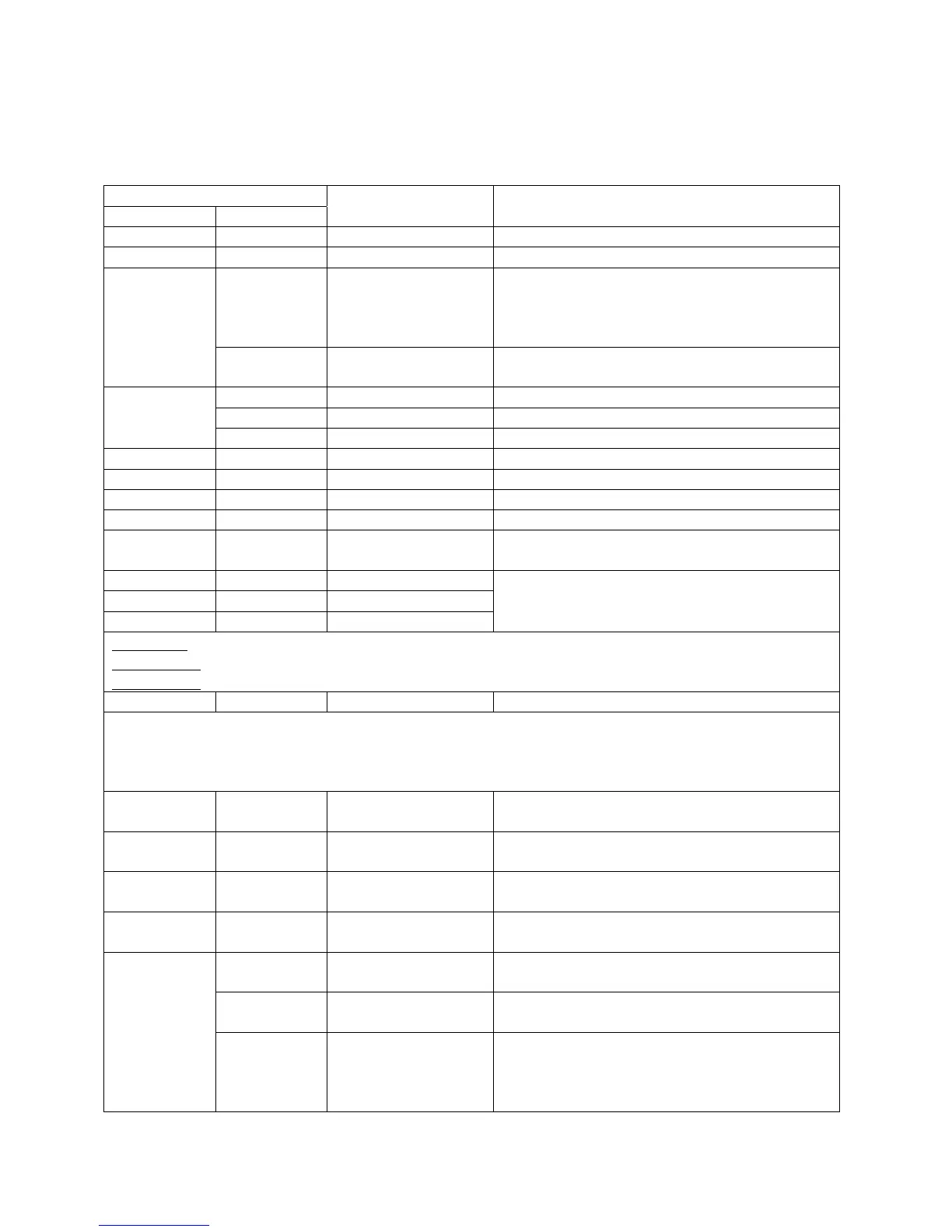
Diagnostic Points on Printed Circuit Board
Measurement Point
Connection Wire Color
Normal Value What you are checking?
I – J AC 90 – 110V Do you have power to the control board?
U W1 – W2 50K Ω – 500K Ω Is the Over Heat Film Wrap OK?
BR1 – BK2 DC 2 - 5V (pulse)
More than 1,310
pulses/minute is
nominal.
Does the water flow sensor send a pulse?
(Only when water is flowing thru control)
S
R3 – BK2 DC 11 – 17 V Does the water flow sensor have voltage?
(Power ON; no water flow)
B4 – W6 DC 120 – 160 V Does the fan motor have the proper voltage?
R3 – B4 DC 12 - 18 V Does the fan motor have proper voltage?
G
Y1 – B4 DC 4 – 10 (Pulse) Is the fan motor producing a regular pulse?
R W6 – BK3 68
0
F = @ 10.3 KΩ Is the cold water inlet thermistor working?
R Y5 – BK3 104
0
F = @ 4.9 KΩ Is the heat exchanger thermistor working?
R R4 – BK3 104
0
F = @ 4.9 KΩ Is the hot water outlet thermistor working?
R B7 – BK3 68
0
F = @ 10.3 KΩ Is the ambient air thermistor working?
R R1 – BK2 DC 1.5 - 14 V
40 – 80Ω
Is the P.G.F.R. valve operating?
(Proportional Gas Flow Regulating Valve)
L R1 – GND AC 1 – 100 V
M W1 – GND AC 1– 100 V
T B1 – GND AC 1 – 100 V
Are the three flame rods detecting flame?
Flame Rod 1 is the white wire and goes to the right front half burner.
Flame Rod 2
is the red wire and goes to the right rear half burner.
Flame Rod 3
is the blue wire and goes to the left burner. (74 series only)
H GY2 – GY5 AC 90 - 110 V Is the igniter working properly
All models except RTG66: These are the two green wires at connector H. They are the two green wires
to the by by-pass solenoid on the water flow valve. When the cold water bypass solenoid is closed, must
be 0 volts DC. (Remote set at 118F ~ 180F). When the cold water bypass opens, voltage reads about 80
volts DC. (Remote is set to 100F~116F).
K Y1- BK5 DC 75 - 100 V
.8 – 2.2. KΩ
Is the solenoid (SV0) working?
(Primary fuel inlet to gas valve)
K W2- BK5 DC 75 - 100 V
.8 – 2.2. KΩ
Is the solenoid valve (SV1) working?
(Fuel to ODS and front right burner)
K R3- BK5 DC 75 - 100 V
.8 – 2.2. KΩ
Is the solenoid valve (SV2) working?
(Fuel to back right burner)
K B4- BK5 DC 75 - 100 V
.8 – 2.2. KΩ
Is the solenoid valve (SV3) working?
(Fuel to left side burner)
W2 – BK8 DC 8 – 16V Does the water volume control motor have
proper voltage?
R7 – BK8 DC 8 – 16V Does the water volume control motor have
proper voltage?
B
GR6 – BK8 Less than 1V DC
(Limiter on)
DC4 – 6 V (Limiter
Off)
Is the water volume control switch OK?
 Loading...