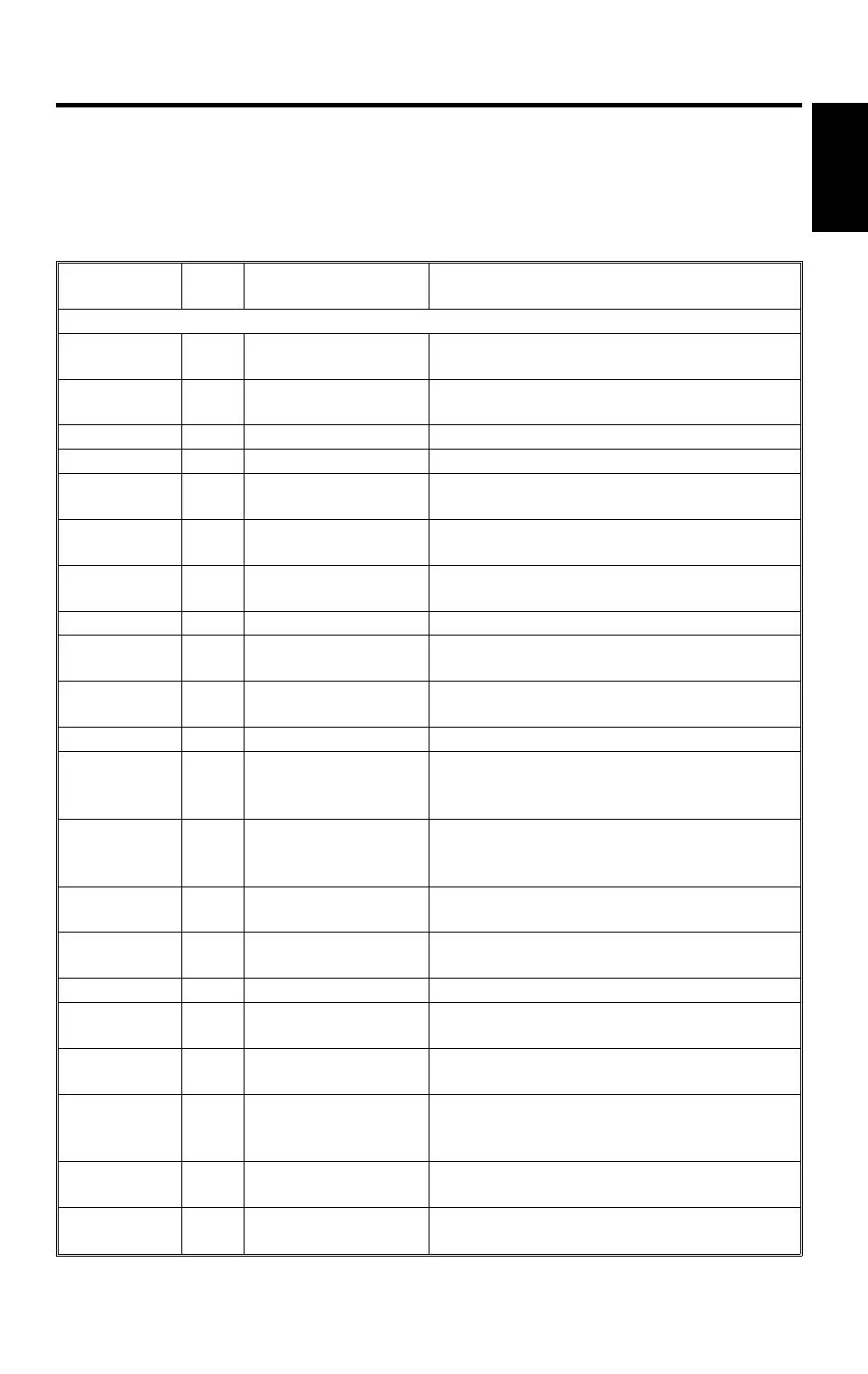
3. ELECTRICAL COMPONENT DESCRIPTIONS
Refer to the electrical component layout and the point-to-point diagram on the
waterproof paper in the pocket for the locations of these components.
✽: New or modified components.
Symbol Index
No.
Description Note
Printed Circuit Boards
PCB1 90
SCU Controls all copier functions both directly or
through other control boards.
PCB2 89
AC Drive Provides ac power to the exposure lamp and
fusing lamps.
PCB3 92 DC Power Supply Provides dc power.
PCB4 93 BCU Controls the mechanical parts of the printer.
PCB5 80
Charge High Voltage
Supply
Supplies high voltage to the charge corona
unit.
PCB6 85
High Voltage Control Controls the high voltage boards and the
quenching lamp.
PCB7 87
Operation Panel Controls the touch panel display and LED
matrix, and monitors the key matrix.
PCB8 95 Scanner Drive Drives the scanner motor.
PCB9 81
EX-IPU Processes the video signal from the SBU
and sends the video signal to the LD unit.
PCB10 84
SBU Contains the CCD, and outputs a video
signal to the EX-IPU board.
PCB11 94 Lamp Stabilizer Provides dc power for the exposure lamp.
PCB12 86
Main Scan
Synchronization
Detector - 1
Detects the laser beam at the start of the
main scan.
PCB13 83
Main Scan
Synchronization
Detector - 2
Detects the laser beam at the end of the
main scan.
PCB14 31
Transfer High
Voltage
Supplies high voltage to the transfer belt.
PCB15 33
Development Bias
Power Pack
Supplies high voltage to the development
roller.
PCB16 40 Duplex Control Controls the operation of the duplex tray.
PCB17 N/A
Liquid Crystal Display Controls the guidance display and displays
guidance for machine operation.
PCB18 51
LCT Interface Interfaces the LCT control signal between
the main board and the LCT.
PCB19 91
Relay Board Switches ac power to either the dc drive
board (if the main switch is on) or to the
heaters (if the main switch is off).
PCB20 7
Laser Diode Drive Controls the laser diode.
✽
PCB21 96
Extension Board Transfers control signals between the SCU
and the dummy board.
A195
Copier
25 April 1997 ELECTRICAL COMPONENT DESCRIPTIONS
5
 Loading...