19
INSTALLATION
4.6 Water Quality Guidelines
Excessive water hardness causing a lime buildup in the stainless
steel coils or tubes is not a fault of the appliance and is not covered
by warranty. Water hardness must fall within the following limits:
Parameters Units Value
General feature - Colorless, no sediment
PH value PH Min 6.5; Max 9
Dissolved Oxygen mg/l < 0,05
Total iron (Fe) mg/l < 0,3
Total copper (Cu) mg/l < 0,1
Na
2SO3 mg/l < 10
N
2H4 mg/l < 3
PO
4 mg/l < 15
CaCO
3 ppm Min 50 ; Max 150
Trisodium Phosphate ppm absent
Chlorine ppm < 100
Pressure PSI Min 7.25; Max 80
Glycol % Max 50% (only propylene glycol)
− Avoid an automatic water ll system.
− Use only untreated water to ll the system.
− Do not use TSP (tri-sodium phosphate)
− Do not use ll water treated with salt bedding type
exchangers (ion exchanger).
− Consult a local water treatment specialist for
recommendations if any of the above table is outside the
stated ranges.
− When using oxygen permeable PEX, the system must be
separated from the boiler by a heat exchanger.
− A correctly sized and working expansion vessel must be
installed.
− Excessive ow can cause erosion damage to the heat
exchanger.
9
CAUTION: For freeze protection use only propylene glycol, with
scale inhibitors, with a maximum volume [concentration] of
50% of glycol. Frost protection and inhibitor level has to be
checked annually during the regular scheduled maintenance
of the condensing boiler.
9
CAUTION: The boiler, when used in connection with a
refrigeration system, must be installed so the chilled medium
is piped in parallel with the boiler with appropriate valves to
prevent the chilled medium from entering the boiler.
9
CAUTION: The boiler piping system of a hot water boiler
connected to heating coils located in air handling units where
they may be exposed to refrigerated air circulation must be
equipped with ow control valves or other automatic means
to prevent gravity circulation of the boiler water during the
cooling cycle. A minimum water pressure is required for
optimum performance. Minimum water pressure required: 7.25
psi (0.5 bar).
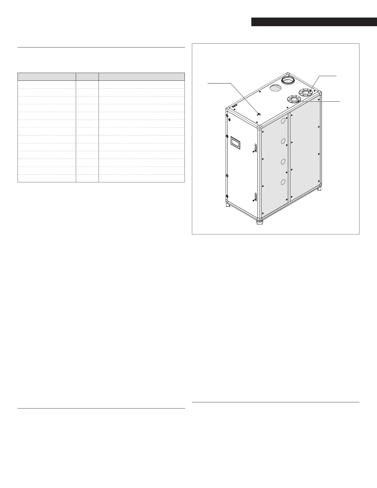
4.7 Supply and Return Piping
The Array Boiler utilizes 3” ANSI anges for models AR 1000 and
AR 1500 and 4” anges for model AR 2000 for the water system
supply and return piping connections. The physical location of the
supply and return piping connections is on the top of the unit as
shown in Fig. 11.
Water
Return
(Inlet)
Water
Supply
(Outlet)
Gas
connection
Fig. 11
Array AR 1000, AR 1500 and AR 2000 Connections
9
CAUTION: Before connecting the boiler to the heating system,
ush the heating system to remove sediment, ux, dirt, and
other foreign matter. The heat exchanger may be damaged by
sediment or corrosion.
9
CAUTION: Do not use cleaning uids that are not compatible
with the boiler materials, including acids (e.g. hydrochloric
acid and/or similar ones) at any concentration.
9
CAUTION: Introducing fresh water to the system increases
the oxygen presence and can cause corrosion of metallic
components. Immediately repair any drips or leaks in the
system to avoid constant introduction of air into the system.
9
CAUTION: Excessive uctuation in pressure changes in the
system can cause fatigue and stress on the heat exchanger.
This is detrimental to the integrity of the boiler and system
components. It is mandatory to maintain a constant operating
pressure.
A minimum water pressure is required for optimum performance.
Minimum water pressure required: 7.25 psi (0.5 bar).
4.8 Low Water Cutoff
A low water protection is installed at two levels:
− boiler level
− heat exchanger level
Boiler level:
a Low Water Cut Off (LWCO) sensor is installed on top of the supply
header of each boiler. To check its functionality, go to the HMI
touchscreen, access the Boiler screen (see section 6.3.3), push
LWCO TEST button and conrm. The error message “33 LWCO/Air
 Loading...