35
COMMISSIONING
5.6 Multiple Boiler Cascade Installation and Start-Up
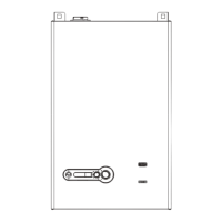
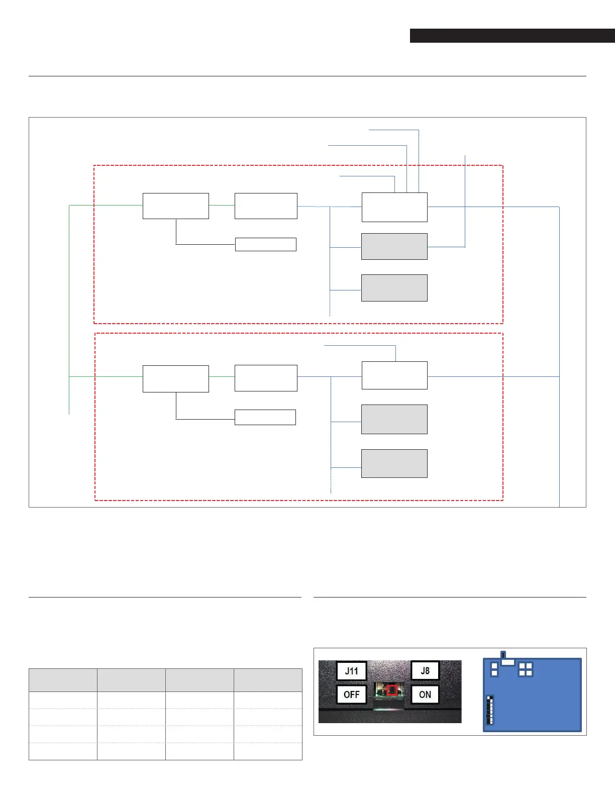
Appendix L shows an example of Array boilers installed in a cascade of three units. The built-in control system is capable of managing
up to 8 boilers as a single, coordinated heating system. The logical schematic is:
Demand: 0-10V / OpenTherm / On-Off
T outside
System sensor D2 is
Cascade system sensor
Boiler sensor
J6 J8 Iso + Power
S1 = on
J8
S1 = off MANAGING
BOILER
J8
S1 = off
Boiler sensor
J6 J8 Iso
S1 = off
J8 DEPENDENT
BMS
RS485
S1 = off BOILER
J8
S1 = off
90xMN - D1
Boiler manager &
Cascade manager
90xMN
- D2
90xMN
- D3
900PBTouch Screen
Max. 8 burners or units
900PB
Max. 8 burners or units
Power Supply
Touch Screen
90xMN - D1
Boiler manager &
Cascade manager
90xMN
- D2
90xMN
- D3
Fig. 56
Cascade installation scheme
After connecting the electrical wiring of the Managing controllers of each boiler of the cascade (through the “Cascade link” connections
on the Low voltage terminal strips), the following steps must be performed.
5.7 Boiler Cascade: Set Boiler Address
Assign the Boiler Address in the managing control of each boiler in
the cascade, following the path below on the Sevice display:
Menu->Setting->Boiler Settings->Boiler Cascade Settings->(73)
Boiler Address
BOILER
(73) Boiler
Address
BOILER
(73) Boiler
Address
Managing Managing Dependent 4 Dep. 5
Dependent 1 Dep. 2 Dependent 5 Dep. 6
Dependent 2 Dep. 3 Dependent 6 Dep. 7
Dependent 3 Dep. 4 Dependent 7 Dep. 8
5.7.1 Boiler Cascade: Set Power switch S1
On the Managing controller of the Cascade Managing boiler, the
Power Switch S1 must be in ON position (see picture below).
The S1 switch must be in OFF position on all other controllers of the
dependent boilers in the cascade.
Fig. 57
Set Power Switch S1
 Loading...