RIGOL Chapter 2 Performance Verification Test
2-20 DSG800 Performance Verification Guide
10 MHz Reference Input Amplitude Range Test
Specification
10 MHz Reference Input Amplitude Range
Specification 0 dBm to +10 dBm
Test Devices
1. Function/Arbitrary Waveform Generator × 1
2. Signal Analyzer × 1
3. Dual-BNC Cable × 2
4. N-BNC Cable × 1
Test Connection Diagram
10MHz OUT
DSG800
DG
4000
N9030A
CH1 CH2
10MHz IN
10MHz IN
RF IN
Dual-
BNC Cable
Dual-BNC Cable
N-BNC Cable
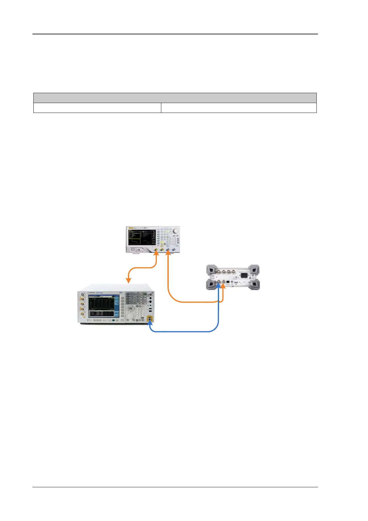
Figure 2-8 10 MHz Reference Input Amplitude Range Test Connection Diagram
Test Procedures
1. Connect the [CH1] output terminal of the function/arbitrary waveform generator with the
[10MHz IN] input terminal of the signal analyzer. Set the signal analyzer to external
reference; set the frequency and amplitude of CH1 of the function/arbitrary waveform
generator to 10 MHz and +5 dBm respectively and turn on the output to synchronize the
function/arbitrary waveform generator and signal analyzer, as shown in Figure 2-8.
Note: The 10 MHz signal output from the function/arbitrary waveform generator must have
relatively higher accuracy (with lower than ±5 ppm deviation); otherwise, this specification
cannot be measured.
 Loading...