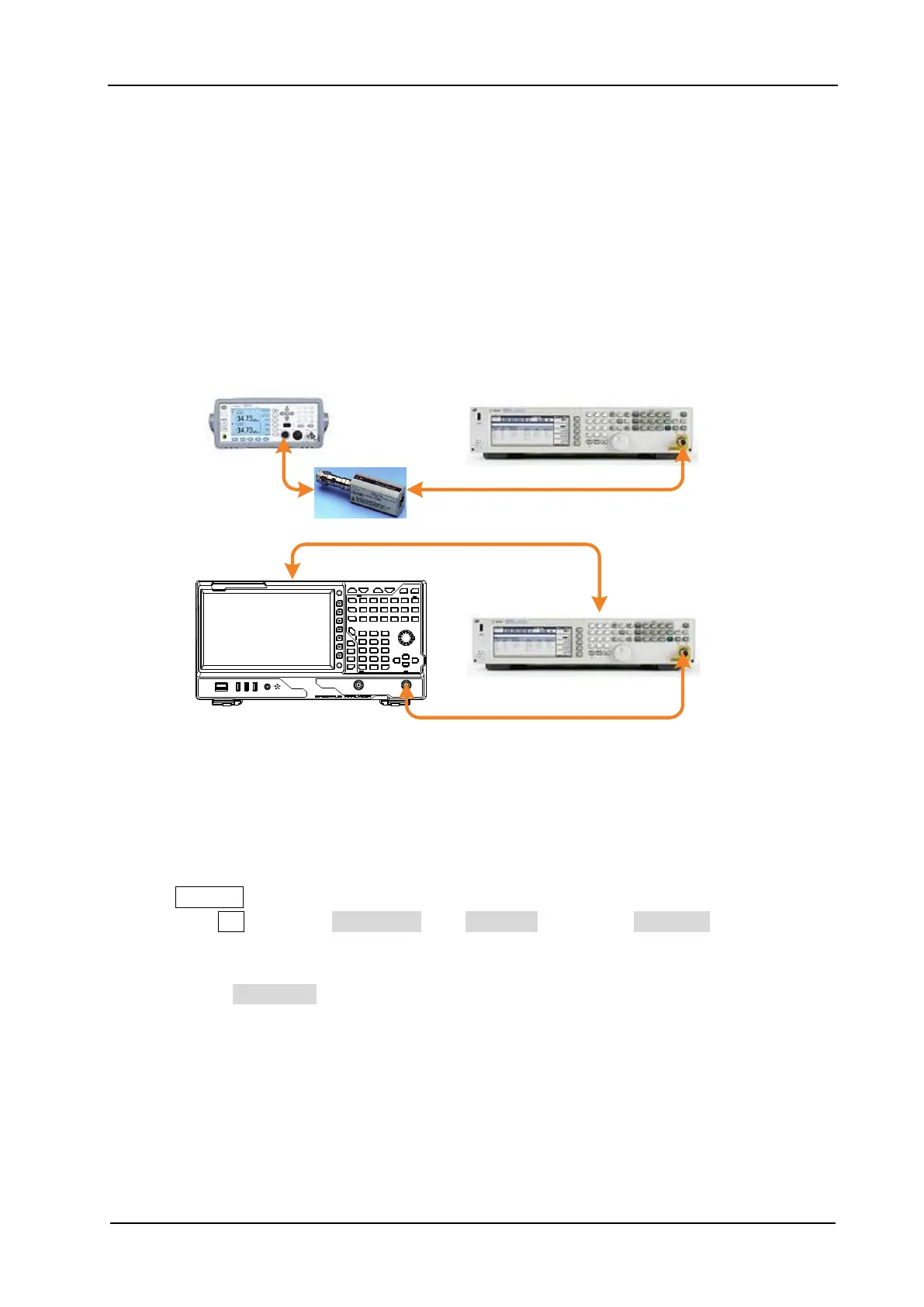
Figure 2-4 Frequency Response Test Connection Diagram
Test Procedures
1. Calibrate the power meter:
a) Connect the power sensor with the [REF] terminal and Channel A of the power meter. Press
Channel and set the frequency of Channel A to 50 MHz.
b) Press Cal and enable Power Ref in the Zero/Cal menu. Press Zero+Cal and wait for the
calibration to finish; then, observe whether the measurement value of the power meter is a
0 dBm, 50 MHz signal.
c) Disable Power Ref.
2. Connect the output terminal of the signal generator with the power sensor, as shown in Figure
2-4 (a).
3. Set the output frequency of the signal generator to 50 MHz; set the amplitude to -10 dBm.
4. Measure the output amplitude of the signal generator by using the power meter and record the
 Loading...