FAQ – CMC III
Page 19 of 24
Installation and wiring
The infrared sensors do not detect the door in its closed state, what needs to be
considered?
The infra-red sensors have only a specific working range. In particular for the two external
sensors, 7030.120 infrared access sensor and 7030.200 CAN bus Access care must be
taken to ensure that the sensors are not placed too near the door because otherwise the
infrared light can no longer be reflected correctly. An overview of the possible working ranges
is shown in the following table:
In the delivered state, a protective foil that covers the front of the sensor protects it from
transport damage. This foil must be removed when the sensor is installed.
What is the pin assignment of the 7030.190 universal sensor when the S
0
or the
Wiegand interface is used?
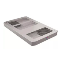
If the 7030.190 universal sensor is used as S
0
interface, pin 5 or pin 6 (pulse) and pin 2
(GND) must be used. The universal sensor so permits the connection of two devices with S
0
interface:
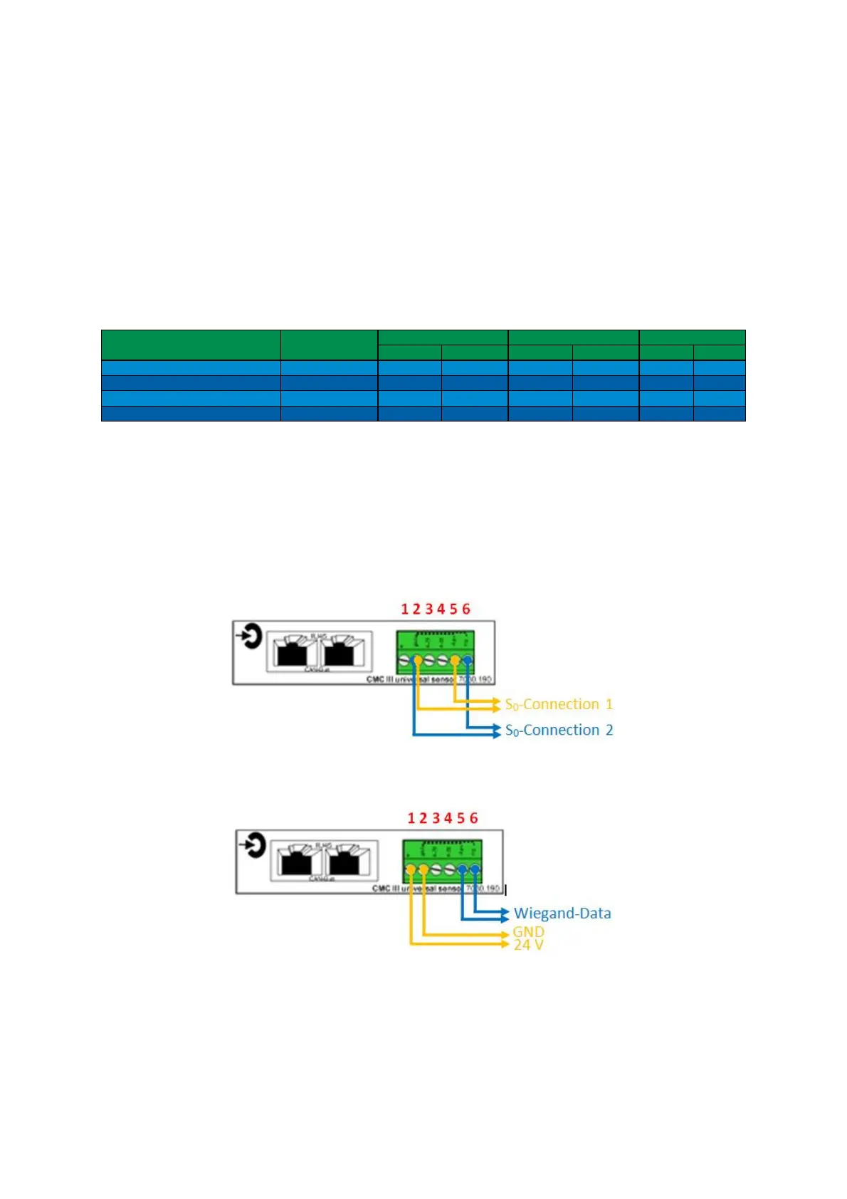
If the "7030.190 universal sensor" is used as Wiegand interface, pin 5 and pin 6 must be
used as data lines. Consequently, only one reader device with Wiegand interface can be
connected to a universal sensor. Pin 1 and pin 2 can also serve as 24 V power source:
min (mm) max (mm) min (mm) max (mm) min (mm)
7030000 20 85 20 140 20 160
7030010 20 85 20 140 20 160
7030120 16 80 16 90 16 100
7030200 25 40 25 70 25 100
CMC III Processing Unit Compact
CMC III Infrarot-Zugangssensor
 Loading...