Logic Module, Internal CompactFlash, and RAM 13
Publication 2711P-IN004J-EN-P - September 2009
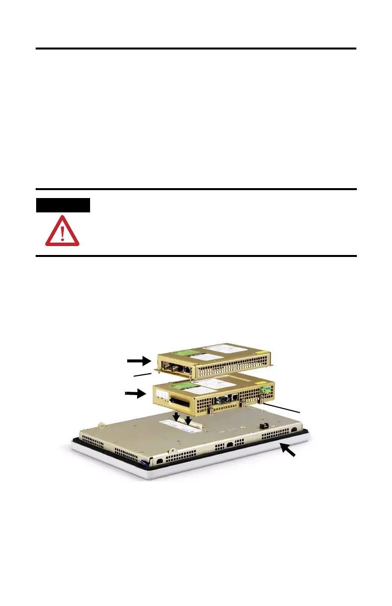
Replace a Logic Module
Before replacing the logic module, you must remove the communication module, if attached.
Remove the internal CompactFlash card and RAM from the logic module if you want to
reuse the memory in the new logic module.
Follow these steps to replace the logic module.
1. Disconnect power from the terminal.
2. Disconnect all power and communication cables.
3. Set the terminal display-side down on a clean, flat, stable surface to prevent scratches
if the terminal is removed from a panel.
4. Remove the four screws that secure the communication module, if attached, to the
logic module and carefully lift the communication module away from the logic
module.
5. Loosen the six captive screws that secure the logic module.
6. Carefully lift the logic module away from the back of the display module.
WARNING
Do not connect or disconnect any communication cable with power applied to this device
or any device on the network. An electrical arc could cause an explosion in hazardous
location installations. Be sure that power is removed or the area is nonhazardous before
proceeding.
Logic Module
Communication Module
Screw
Screw
Display Module
www.aotewell.com sales04@aotewell.com

 Loading...


