CompactLogix Controllers 7
Publication
1768-IN004D-EN-P - December 2009
Required System Components
You need these parts when installing your controller:
• 1768-L43, 1768-L43S, 1768-L45, or 1768-L45S CompactLogix
controller
• 1768-PA3 or 1768-PB3 power supply
• 1769-ECR end cap
• Mounting screws (M4 or #8 panhead) or one of these
EN 50 022 DIN rails:
– 35 x 7.5 mm (1.38 x 0.30 in.)
– 35 x 15 mm (1.38 x 0.59 in.)
• 1756-CP3 serial cable (or make your own)
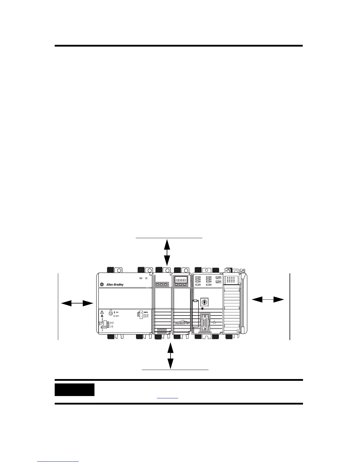
Clearance Requirements
Allow for the minimum clearance from enclosure walls, wireways,
and other equipment.
IMPORTANT
These minimum clearances keep the modules cool enough in most situations.
See Specifications on page 32
for the acceptable temperature range.
31609-M
Power
OUT
L1
L2/N
90 mm
(3.54 in.)
105 mm (4.13 in.)
90 mm
(3.54 in.)
105 mm (4.13 in.)
 Loading...