16
7 WHAT TO DO IF...
If the PNC-900 doesn't run...
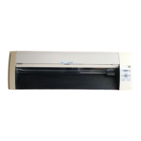
PNC-900
• Is the PNC-900 power on?
Turn on the power.
• Is the unit in SETUP status (the SETUP LED is lit)?
If the SETUP LED is not illuminated, make sure the sheet is loaded correctly and press the SETUP key to illuminate the
SETUP LED.
• Is the PAUSE LED illuminated?
If the PAUSE key has been pressed and the PAUSE LED is lit up, the unit has been paused (see "Pausing Cutting Opera-
tions" on page 10).
If you want to resume cutting, press the PAUSE key again. The PAUSE LED is extinguished, and cutting resumes.
If you want to terminate cutting, first stop the transmission of cutting instructions from the computer to the PNC-900. Then
press the SETUP key. This deletes the cutting instructions that have already been sent from the computer to the PNC-900,
and cutting is stopped.
• If connected via the serial port, do the communication parameters for the PNC-900 match those of the computer?
Set the DIP switches correctly (see "4-2 DIP Switch Settings" on page 5.)
Computer
• Is the computer set up correctly?
Check the following items:
• DIP switches • Memory switches • Interface board • Communication parameters
• Other settings
Read the computer user’s manual and set it up correctly.
Connection cable
• Are the computer and the PNC-900 linked with the right cable?
The type of cable you need is determined by your computer and the software you are using. Even if the computer is the same,
running different software may require a different cable. Use the cable specified in your software.
• Is the cable making a secure connection?
Connect securely.
Software
• Is the OS set up correctly?
Check the following items:
• Output port selection • Output device selection • Output port open • Communication parameters
• Other settings
Check the OS user’s manual and set it up correctly.
• Are the application software settings correct?
Check the following items:
• Output device specifications (select a device name that matches the instruction system. If the wrong device is
selected an incorrect instruction may be output, resulting in an error).
• Communication parameters
• Other settings
Check the software user’s manual and set it up correctly.
The POWER/ERROR LED is blinking
If there is an error in the data downloaded to the PNC-900 from the computer, the PNC-900 generates an error (the POWER/
ERROR LED begins to blink), and cutting cannot be carried out. The error can be canceled by switching off the power.
After turning off the power, check the following.
• If you are using application software, has the correct output device been selected?
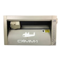
Select "PNC-900" as the output device. If this selection is not available, select any model in the CAMM-1 series (the
PNC-1900/1600, PNC-1800, PNC-1100, PNC-1000A, or PNC-1000).
 Loading...