3 x Installation
20
FA ROTEX Solaris RPS3 25M - 03/2010
3.8 Electrical connection
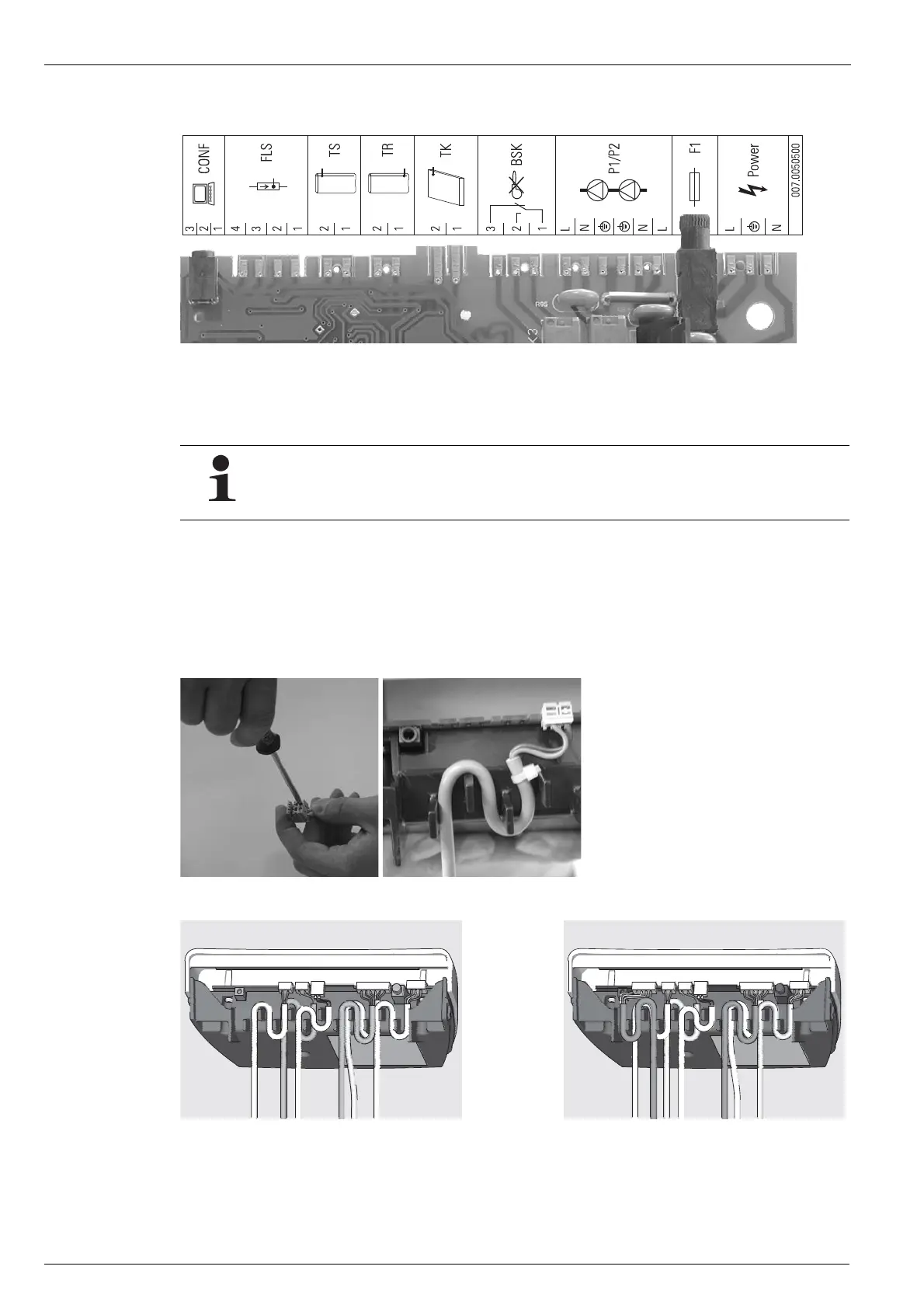
1. Clamp the collector temperature sensor cable to the connector.
2. Clip the connector onto the edge of the control system circuit board at position "TK" (2-pin, see Image 3-24).
3. Route the collector temperature sensor cable through the labyrinth to prevent strain on the cable.
4. Clip the mains and pump connection cables (premounted on the terminal block) to the edge of the control system circuit board
at positions "Power" and "P1/P2." The connectors are polarised to prevent errors.
5. Place controller into the housing baseplate from above.
• Make sure that the loops in the cable are pointing downwards (as shown in Image 3-27 to Image 3-28).
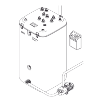
BSK Burner inhibit contact
CONF Programming socket for
software update
FLS FlowSensor
F1 Fuse
TK Collector temperature sensor
TR Return flow temperature sensor
TS Storage tank temperature sensor
P1 Circulation pump
P2 Optional
Booster pump
Power Mains supply
Illustration 3-24 Terminal assignment controller PCB
The storage tank temperature sensor and the return flow temperature sensor are already connected to the
Solaris R3 controller at the factory.
Illustration 3-25 Step 1 Illustration 3-26 Steps 2+3
Illustration 3-27 Basic cabling: sensors for storage tank, return and
collector sensor, pump supply, mains supply
Illustration 3-28 Additional cabling with FlowSensor
 Loading...