Hardware Installation and Reference Guide Product Installation
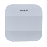
For RG-MTFi-M520 with a single 3G/4G module, insert the SIM card into SIM Card-1 slot with adapter. For
RG-MTFi-M520 with dual 3G/4G modules, insert the SIM cards into SIM Card-1 slot and SIM Card-2 slot with
adapters.
To prevent SIM card from missing, fasten the anti-theft panel to the front panel using four M3 hexagon socket-head
screws after the SIM card is inserted.
The following figure shows appearance of the anti-theft panel.
Figure 2-2 Anti-theft Panel
2.2.2 Installing the Antenna
Screw the antennas delivered with RG-MTFi-M520 into corresponding antenna connectors on the rear panel, and make
sure that the antennas are fastened. The antennas are provided with 3M adhesive, and may be attached near the window.
2.2.3 Installing the Power Cable
Connect the DC aviation plug to RG-MTFi-M520 properly, and fasten the aviation plug by rotating the nut.
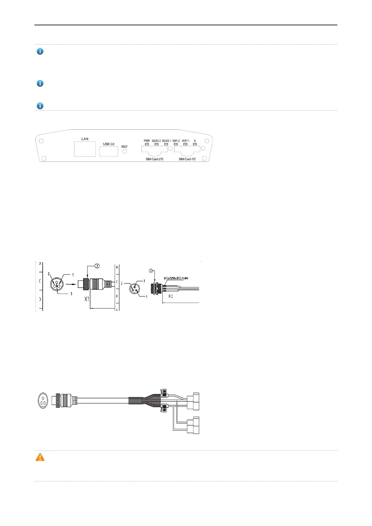
Figure 2-3 Connecting the DC Aviation Plug to RG-MTFi-M520
Left: DC aviation plug Right: Aviation plug on RG-MTFi-M520
The following figure shows the power cable of RG-MTFi-M520 with two types of vehicle-mounted connector terminals.
Select a connector terminal according to actual requirements, remove the stopple of the terminal, and properly connect
the terminal to a matched terminal in the vehicle (VCC/yellow, ACC/red, and GND/black should be correspondingly
connected). Do not remove the stopple of the other unused terminals to prevent exposing metal wires.
Figure 2-4 Power Cable of RG-MTFi-M520
Make sure that output of the power supply and power fall within an available range before the connection, and use
the multimeter to check whether the vehicle power supply is 12 V or 24 V and whether the vehicle power cable is
properly connected.
 Loading...