User Manual User Manual
3029
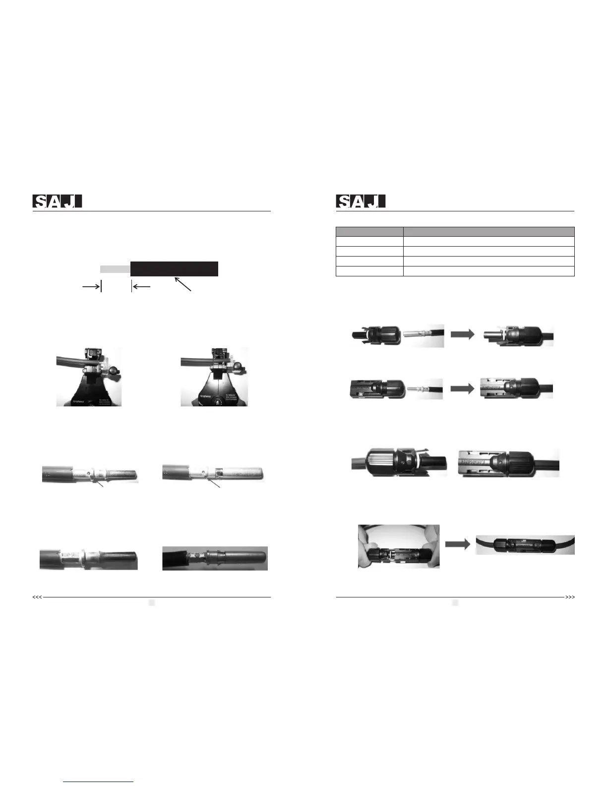
4. Insert contact cable assembly into back of male and female connector. A
“click” should be heard or felt when the contact cable assembly is seated
correctly. See below figures.
5. Wrest the cap by using the torque of 2.6~2.9N·m.
6. After wrested the cap tightly, align the 2 half connectors and mate them
together by hand until a “click” is heard or felt.
Female side connector (F)
Figure 6.16
Male side connector (M)
Figure 6.15
Figure 6.17
Figure 6.18
Use specified strip tool in this step. Adjust the strip stopper and put the cable in
corresponding notch to strip the length of 7mm. See below figures.
2. Insert stripped cable into contact barrel and insure all conductor strands are
captured in the contact barrel and the conductors are visible in the contact
barrel observation hole. See below figures.
3. Crimp contact barrel by using the hex crimping die. ensure it is fixed.See
below figures.
Figure 6.10 Figure 6.11
Ba rr el o b s er va ti o n h ol e
Conductor should be visible
Ba rr el o b s er va ti o n h ol e
Conductor should be visible
Figure 6.12 Figure 6.13
Figure 6.14
Cable pull – out force requirement
Min. 310 N (70 Lbs)
Min. 400 N (90 Lbs)
Min. 450 N (100 Lbs)
Min. 500 N (110 Lbs)
Cable Size
2.5 mm
4 mm
6 mm
10 mm
2
2
2
2
Crimped pin contact Crimped socket contact
Pin contact
Socket contact
Cable requirements:
Assembly Instructions:
1. Strip the cable with the length 0.276 inches (9/32")-(7mm) and please be
careful NOT to nick conductors.
Figure 6.9
Cable
0.276 inches(9/32")-(7mm)
 Loading...