ENGLISH
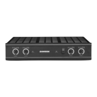
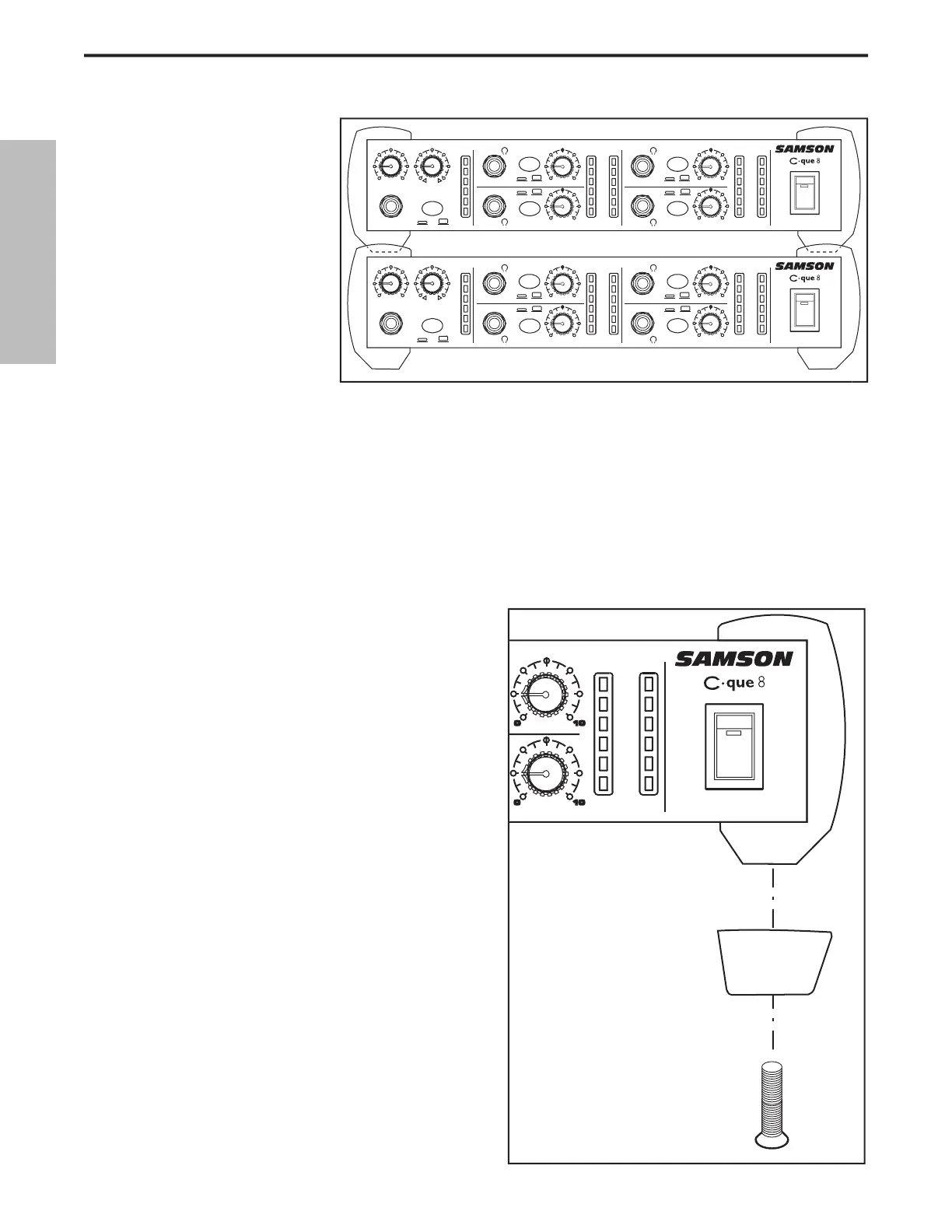
You can install the tilting rubber feet included
with your C que 8 so that you can set the unit at a
comfortable operating angle on a workstation or
desktop. Follow the simple instructions below to
install the tilting feet.
• Remove the bottom screw from right front
• Identify the right tilting foot by the locat-
ing “R” marking on the inside top.
• Position the angled foot under the right
bumper as shown in the drawing.
• Use the included 3 x 16mm screw to attach
• Repeat the steps above for the front left
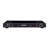
You can stack one C cue 8,
or any other Samson C Class
units, on top of each other by
simply lining up the bumpers.
Important Note: When stacking
the C que 8, be sure that only
the bottom unit has the tilting
• Remove the bottom screw from right front bumper.
• Identify the right tilting foot by the locating “R” marking on the inside top.
• Position the angled foot under the right bumper as shown in the drawing.
MAIN
INJECT
VOLUME BALANCE
2 CH
STEREO
SHAPE
OUT
SHAPE
OUT
CH 1
OL
0
-6
-12
-18
-24
OL
0
-6
-12
-18
-24
CH 1
CH 2
SHAPE
OUT
SHAPE
OUT
OL
0
-6
-12
-18
-24
CH 3 CH 4
4 CHANNEL
HEADPHONE AM
P
CH 2
CH 3
CH 4
VOLUME
VOLUME VOLUME
VOLUME
0 1
0
0 1
0
0 1
0
0 10
0 1
0
L R
MAIN
INJECT
VOLUME BALANCE
2 CH
STEREO
SHAPE
OUT
SHAPE
OUT
CH 1
OL
0
-6
-12
-18
-24
OL
0
-6
-12
-18
-24
CH 1
CH 2
SHAPE
OUT
SHAPE
OUT
OL
0
-6
-12
-18
-24
CH 3 CH 4
4 CHANNEL
HEADPHONE AM
P
CH 2
CH 3
CH 4
VOLUME
VOLUME VOLUME
VOLUME
0 1
0
0 10
0 1
0
0 1
0
0 1
0
L R
 Loading...