Wiring
General
(@JR
’
@
2
Ground
wire(Black)
WC)
m
3
+lZV
Accessory/Ignition
wire(Red)
(Es.
UP)
EB
4
+12V
Constant power supply
wire(Yellow)
(P.ANT)
EII
!j Power antenna control
wire(Blue)
,
-
-
-
-
4-Speaker system
-
-
./
,
-
-
-
-
2-Speaker system
-
-
-\
1
5B
iB
;
;
Front Left I
Speaker I j
Front Left I
lp(
I ’
Speaker ;
Front Right
I
:
Speaker
I ;
Front Right
I
Speaker :
Rear
Left
:
Speaker :
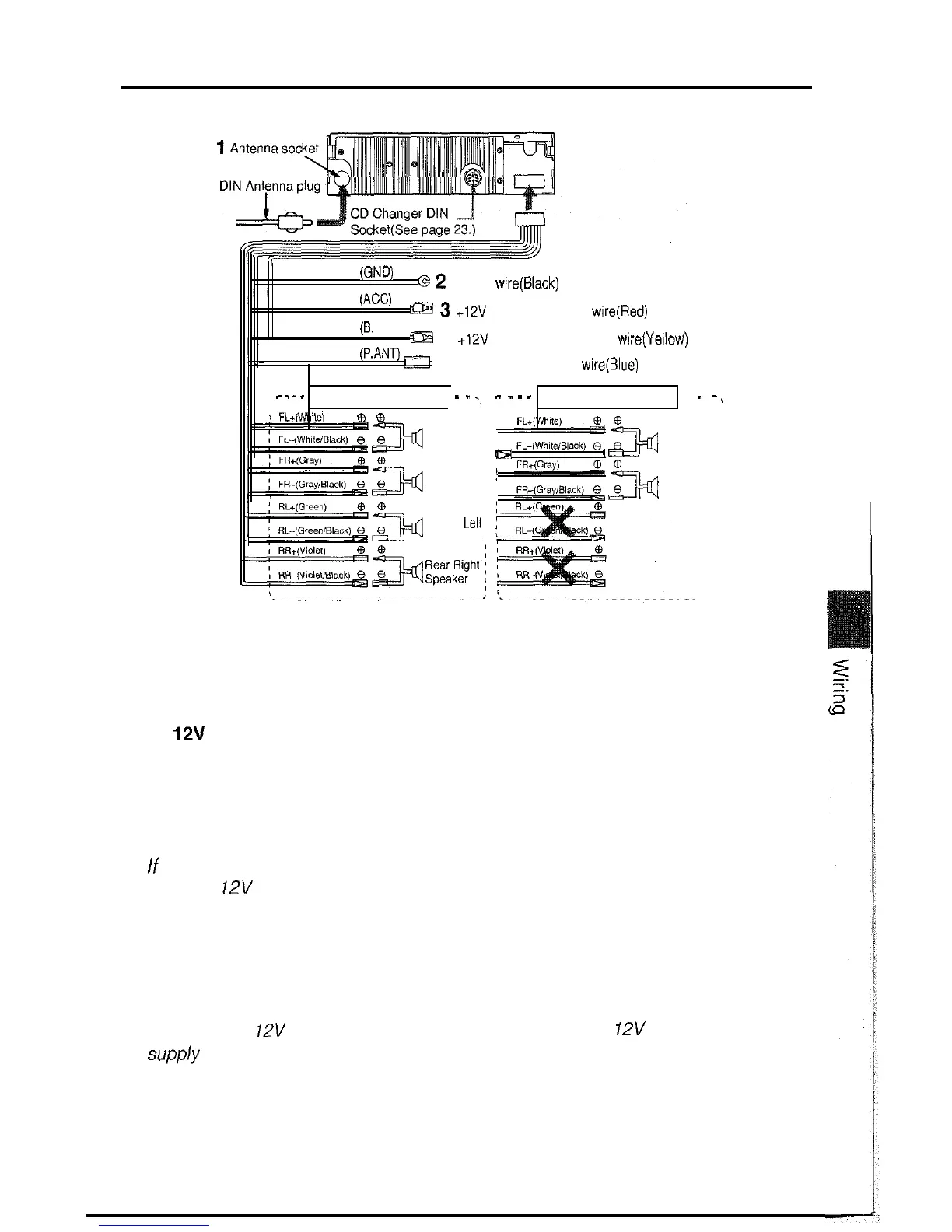
1. Antenna socket
Insert the DIN Antenna plug installed in your vehicle into this socket.
2. Ground wire (Black)
Connect this wire to the vehicle chassis.
3. + 12V Accessory/Ignition wire (Red)
Connect this wire to
a
terminal that receives power while the ignition switch is ON
or in the Accessory (ACC) position.
Never connect the wire to the car battery directly or the car battery may be
drained.
Note:
If
the vehicle does not have an ACC terminal, connect this wire to a terminal which
receives
12V
power while the ignition switch is On, and stands 4A or more of elec-
tric current.
4. + 12V Constant power supply wire (Yellow)
Connect this wire to + 12V power terminal that receives power continuously, and
stands 4A or more of electric current .
Note:
Both of the +
12V
Accessory/Ignition wire (Red) and the +
12V
Constant power
supp/y wire (Yellow) should be connected
to their
respective
terminals
to operate
the unit.
5. Power antenna control wire (Blue)
Connect this wire to the control terminal of Power antenna. When not using a
Power antenna, this wire is not used.
22
 Loading...