- 59 -
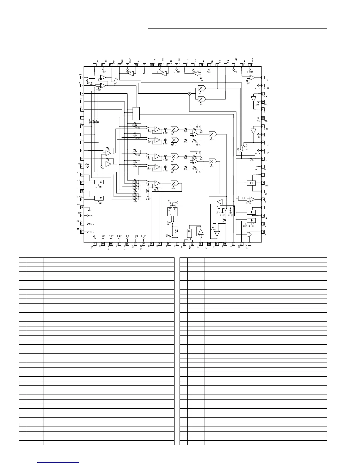
IC BLOCK DIAGRAM & DESCRIPTION
- DVD LOADER section -
IC100 LA9702WL-MPB (Front End Processor forDVD Player)
No Name Description
1 RFN RF signal - input
2 RFP RF signal + input
3 PD1 Pickup signal input
4 PD2 Pickup signal input
5 PD3 Pickup signal input
6 PD4 Pickup signal input
7 PD5 Pickup signal input
8 PD6 Pickup signal input
9 PD7 Pickup signal input
10 PD8 Pickup signal input
11 PD9 Pickup signal input
12 VCC Power (Servo signal)
13 LDD1 APC1 output
14 LDS1 APC1 monitor voltage input
15 LDD2 APC2 output
16 LDS2 APC2 monitor voltage input
17 GND GND. (Servo signal)
18 SGC Servo gain control terminal (RREC, FE, TE)
19 FEBL Focus balance adjusting terminal
20 TEBL Tracking balance adjusting terminal
21 VGA RF gain adjusting terminal
22 BST Equalizer boost adjusting terminal
23 FOST Focus offset adjusting terminal
24 TOST Tracking offset adjusting terminal
25 BCATH BCA threshold adjusting terminal
26 REFI Standard voltage setting terminal
27 SREF standard voltage output for servo signal
28 RREC Reflection output
29 FE Focus error output
30 TE Tracking error output
31 THC Condencer connection terminal to setting TE hold time constant
32 WO Wobble output terminal
33 ISET Resistance connection terminal to setting BPF center frequency
34 WOI Push-pull signal input
35 WOO Push-pull signal output
36 TEO TE gain setting terminal for 3 beam
37 TEN TE gain setting terminal for 3 beam
38 CP Resistance to setting charge pump gain, Condenser connection terminal
39 BHI Resistance connection terminal to setting bottom hold detect parameters
40 RFON RF - output
No. Name Description
41 RFOP RF + output
42 BH RF bottom detection output
43 PHI Resistance connection terminal to setting peak hold detect parameters
44 PH RF peak detect output
45 BCA BCA output
46 DEF Defect output (H: Defect detect)
47 DEFC Condenser connect terminal for defect detect
48 TC Resistance connection terminal to setting defect detect parameters
49 GND GND. (DTP phage)
50 LPC Condenser connection terminal for RF DC servo
51 CPOF Charge pump OFF terminal (H: OFF)
52 EQ02 RF equalizer setting terminal
53 TH Tracking hold (H: Hold)
54 EQL2 RF equalizer setting terminal
55 VCC Power supply (DTP phage)
56 EQO4 RF equalizer setting terminal
57 XHTR Tracking, Bottom detect band select (L: High band)
58 EQI4 RF equalizer setting terminal
59 XQBH Bottom detect time constant select (L: High speed)
60 EQ03 RF equalizer setting terminal
61 EQSCT Equalizer select (H: 77 pin selection, L:52 pin selection)
62 EQI3 RF equalizer setting terminal
63 DPD/TE DPD, 3 beam tracking select (H: DPD)
64 RF02 RF output
65 RF01 RF output
66 VCC Power supply (RF phage)
67 EQI1 RF equalizer setting terminal
68 PP/TE 3 beam, push-pull tracking select (L:3 beam)
69 EQ01 RF equalizer setting terminal
70 LDON2 APC2 Laser ON terminal (H: ON)
71 EQI2 RF equalizer setting terminal
72 LDON1 APC1 Laser ON terminal (H: ON)
73 EQ02 RF equalizer setting terminal
74 GND GND. (RF phage)
75 EQL1 RF equalizer setting terminal
76 RFSCT RF input select (H: RF differential input, PP error)
77 EQ01 RF equalizer setting terminal
78 CAO Customer Amplifier output
79 PREF Standard voltage output (for Pick-up)
80 CAN Customer Amplifier input
 Loading...