Connection on PCB
The following shows connections of connector on Temp. Control PCB.
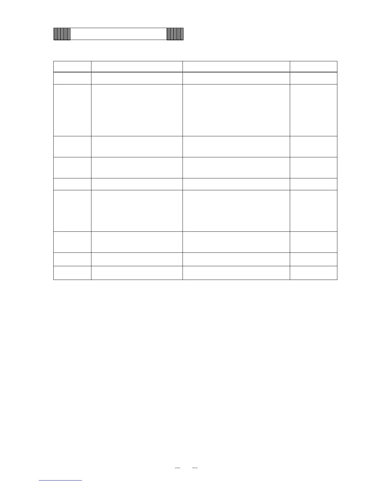
Connector Connects to Usage Voltage
CN1 #1 - #3: Switching power supply To supply the power to PCB.
#1-#3: 12VDC
CN3
Remote alarm terminal
#1: Com
#2: N.O.
#3: N.C.
Output of remote alarm contact
zBetween #1 - #2 is open if the unit
has no alarm condition when the
power is supplied.
zBetween #1 - #3 is closed.
CN4
#1 - #2: Temp. control relay
#3 - #4: Heater relay
To operate compressor L.
To operate cap. tube heater.
#1 - #2: 12VDC
#3 - #4: 12VDC
CN5
#1 - #5: Switch PCB
#6 - #7: Buzzer PCB
To connect with each switch.
To energize buzzer.
CN6 Display PCB To connect with each LED.
CN7
#5 - #6: AT sensor
#7 - #8: Filter sensor
#9 – #10: Cascade sensor
To detect ambient temperature.
To detect temperature on the outlet
pipe of condenser.
To detect cascade temperature.
CN8
#1 - #2: Battery
#3 – #4: Power transformer
Power failure alarm.
#1: 6VDC
#2: GND
CN9 #1 - #2: H comp. relay To operate compressor H #1 - #2: 12VDC
CN11 #1 - #3: Temp. sensor To detect chamber temperature
8
 Loading...