6 7 8 9
1 3 4 5 2
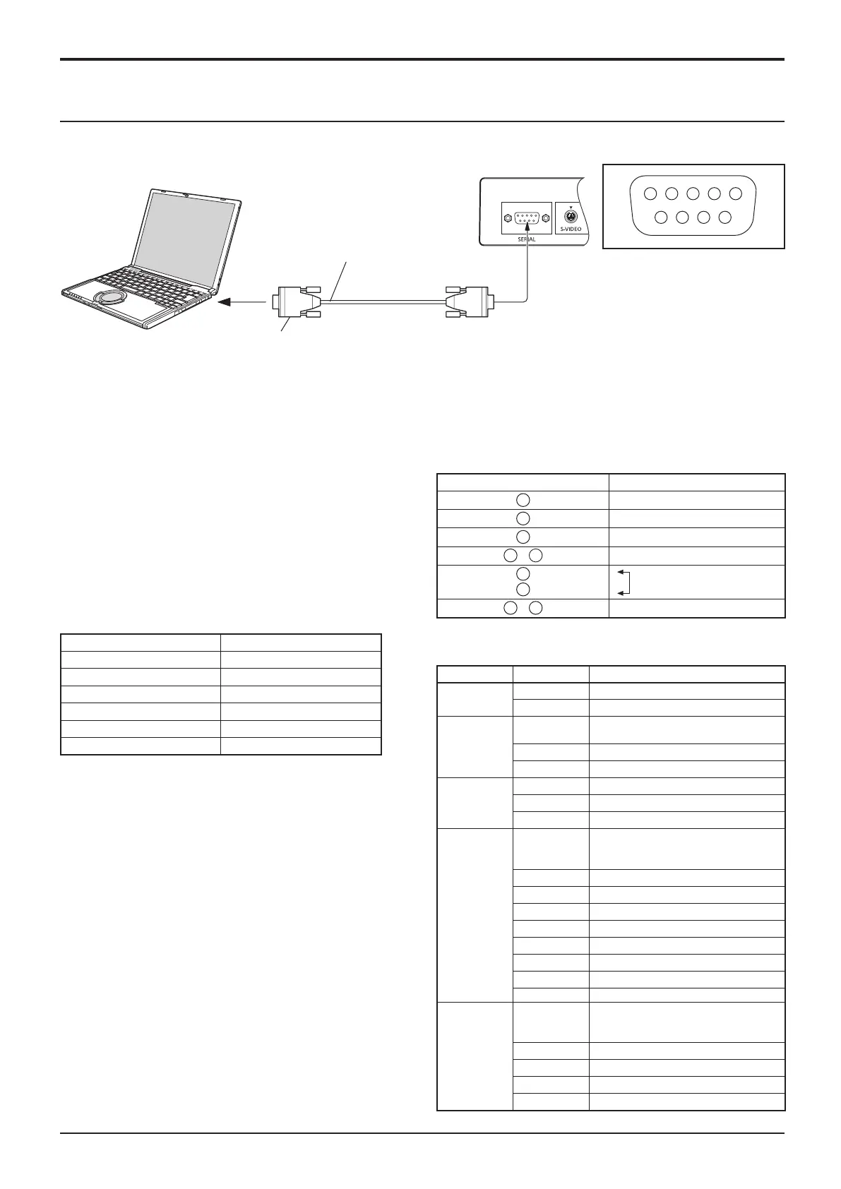
COMPUTER
RS-232C Cross cable
D-sub 9p
(Male)
(Female)
12
SERIAL Terminals connection
Notes:
• Set up the computer to be connected and the communication RS-232C cross cable that connects the SERIAL terminal
with the computer.
• The computer shown is for example purposes only.
• Additional equipment and cables shown are not supplied with this set.
The SERIAL terminal conforms to the RS-232C interface
specication, so that the Display can be controlled by a
computer which is connected to this terminal.
The computer will require software which allows the
sending and receiving of control data which satisfies
the conditions given below. Use a computer application
such as programming language software. Refer to the
documentation for the computer application for details.
The SERIAL terminal is used when the Display is controlled by a computer.
Pin layout for SERIAL Terminal
Basic format for control data
Add parameters as necessary depending on the control
content.
Commands shall be 1 command / 1 line that start with “C”
and end with the carriage return (0x0D).
A space is entered between the command “CF” and the
control instruction.
A space is entered between the command and the
parameter.
Ex) CF_POWER_ON[CR]
_ : space
Notes:
• If a correct command is sent, this unit will send a “000”
command to the computer.
•
If an incorrect command is sent by mistake, this unit will send
a different command apart from “000” to the computer.
• While the power is in “stand-by” mode (power turned off
with remote control), all operations except “CF POWER
ON” will not respond.
Communication parameters
Signal level RS-232C compliant
Synchronization method Asynchronous
Baud rate 9600 bps
Parity None
Character length 8 bits
Stop bit 1 bit
Flow control -
Signal names for D-sub 9P connector
Pin No. Details
2
R X D
3
T X D
5
GND
4
•
6
Non use
7
8
(Shorted in this set)
1
•
9
NC
These signal names are those of computer specications.
Connections
Command
Command Parameter Control details
CF POWER
ON Power ON
OFF Power OFF
CF VOLUME
**
000 - 100 *3 digits
Directly assigns volume level
UP Current volume level +1
DN Current volume level –1
CF MUTE
UP Toggle to select
ON Audio MUTE ON
OFF Audio MUTE OFF
CF INPUT
UP
Toggle to select between:
AV1 ➞ AV2➞ PC ➞ DVI ➞ HDMI1 ➞
HDMI2 ➞ AV1 ➞…
AV1 VIDEO input
AV2 Component/RGB input
AV2YPBPR Component input
AV2RGB RGB input
PC PC input
DVI DVI input
HDMI1 HDMI1 input
HDMI2 HDMI2 input
CF SCREEN UP Toggle to select between:
FULL
➞
NORMAL
➞
ZOOM1
➞
ZOOM2
➞
FULL
➞
…
FULL Full screen
NORMAL Normal screen
ZOOM Zoom 1
ZOOM2 Zoom 2
 Loading...