- 50 -
To enter the service mode
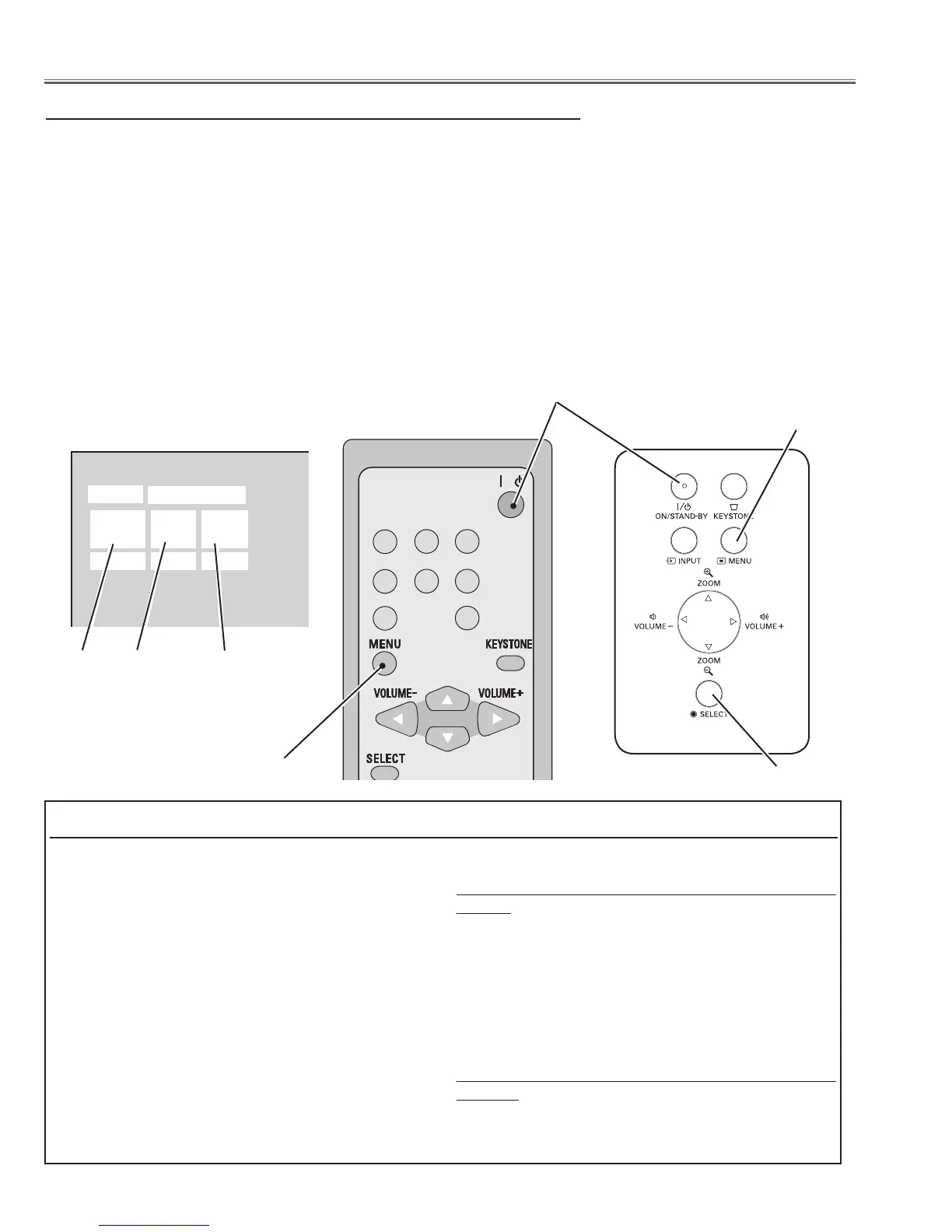
To enter the “Service Mode”, press and hold the MENU and SELECT buttons on the projector simultaneously for 3 seconds.
Or press and hold the MENU button on the remote control unit for more than 20 seconds. The service menu appears on the
screen as follows.
To adjust service data
Select the adjustment group no. by pressing the MENU button (increase) or SELECT button (decrease), and select the
adjustment item no. by pressing the pointer e or d button, and change the data value by pressing the 7 or 8 button.
Refer to the “Service Adjustment Data Table” for further description of adjustment group no., item no. and data value.
To exit the service mode
To exit the service mode, press the ON/STAND-BY button.
Service Adjustment Menu Operation
Memory IC on the main board stores the data for the ser-
vice adjustments, and should not be replaced except for
the case of defective device.
If replaced, the re-adjustments are required following to
the “Electrical Adjustments”.
The data of lamp replacement counter is stored in the
Memory IC.
Please note that the lamp replace counter will be reset
when the memory IC is replaced.
(Lamp replace counter cannot be set to the previous val-
ue.)
● Caution to memory IC replacement
When memory IC is replaced with new one, the CPU writes
down the default data of the service adjustments to the re-
placed IC as the mentioned on the service adjustment ta-
ble. As these data are not the same data as factory shipped
data, it should be required to perform the re-adjustments
following to the “Electrical Adjustments”.
Please note that in this case the lamp replace counter will
be reset.
● Caution of Main Board replacement (in the case mem-
ory IC is not defective)
When the main board is replaced, memory IC should be re-
placed with the one on previous main board. After replace-
ment, it should be required to perform the re-adjustments
following to the “Electrical Adjustments”.
In this case, the lamp replace counter can be kept the value
as before.
Memory IC (IC1391) Replacement
Service Mode
SANYO
Video
KV7A
Input
Ver. R 1.00
Group
55
No.
0
Data
+0
Data value
Item No.
Electrical Adjustments
Group No.
/
COMPUTER
COMPONENT
S-VIDEO
VIDEO
AUTO PC
AUTO SET
NETWORK
1 2
ON / STAND-BY button
MENU button
MENU button
SELECT button
 Loading...