5
AK - 44
CHASSIS
SAFETY PRECAUTIONS
The service of this TV set must be carried out by qualified persons only. Components marked with the warning symbol
on the circuit diagram or on the Parts Listing, are critical for safety and must only be replaced with an identical component.
- Power resistor and fused resistors must be mounted in an identical manner to the original component.
- When servicing this TV, check that the EHT does not exceed 26kV.
TV set switched off:
Make short-circuit between HV-CRT clip and CRT ground layer.
Short C809 before changing IC800 and IC801 or other components in primary side of the SMPS part.
Do not try to test Q801 gate source junction if C809 is charged, your meter will turn on the transistor which will discharge
the capacitor resulting in a drain source short circuit. Do not discharge C809 quickly with a screwdriver etc. The very
high current produced can damage the internal connections of the capacitor causing failure at a later date. Remember
when checking voltages to use a return path on the same side of TR802 for the Voltmeter earth to obtain the correct
readings.
Measurements:
Voltage readings and oscilloscope traces are measured under the following conditions:
Antenna signal’s level is 60dB at the color bar pattern from the TV pattern generator. (100% white, 75% color saturation)
Brightness, contrast, and color are adjusted for normal picture performance.
Mains supply, 220VAC, 50Hz.
DO NOT CHANGE ANY MODULE UNLESS THE SET IS SWITCHED OFF
The mains supply part of the switch mode power supply’s transformer is live.
Use an isolating transformer.
The receiver complies with the safety requirements.
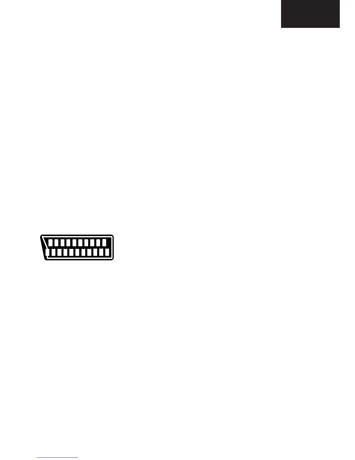
PERI-TV SOCKET
21
21
19
17
15
13
11
9
7
5
3
1
20
18
16
14
12
10
8
6
4
2
SCART PINING
1 Audio right output 0.5 Vrms / 1K
2 Audio right input 0.5 Vrms / 10K
3 Audio left output 0.5 Vrms / 1K
4 Ground AF
5 Ground Blue
6 Audio left input 0.5 Vrms / 10K
7 Blue input 0.7 Vpp / 75 ohm
8 AV switching input 0-12 VDC / 10 K
9 Ground Green
10 -
11 Green input 0.7 Vpp / 75 ohm
12 -
13 Ground Red
14 Ground Blanking
15 Red input 0.7 Vpp / 75 ohm
16 Blanking input 0-0.4 VDC, 1-3 VDC / 75 Ohm
17 Ground CVBS output
18 Ground CVBS input
19 CVBS output 1 Vpp / 75 ohm
20 CVBS input 1 Vpp / 75 ohm
21 Ground
 Loading...