– 7 –
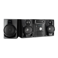
CD-C470H,C470E,C480H/CP-C470H,C470E,C480H
DISASSEMBLY
Caution on Disassembly
Follow the below-mentioned notes when disassembling
the unit and reassembling it, to keep it safe and ensure
excellent performance:
1. Take cassette tape and compact disc out of the unit.
2. Be sure to remove the power supply plug from the wall
outlet before starting to disassemble the unit.
3. Take off nylon bands or wire holders where they need be
removed when disassembling the unit. After servicing
the unit, be sure to rearrange the leads where they were
before disassembling.
4. Take suffcient care on static electricity of integrated
circuits and other circuits when servicing.
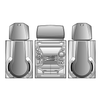
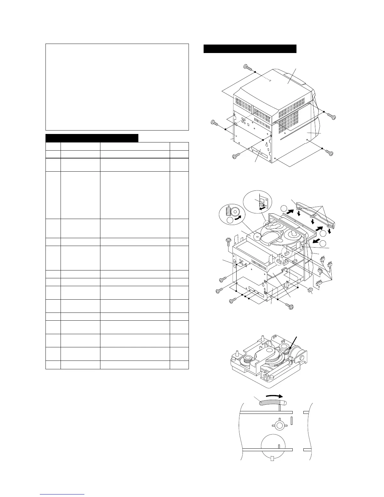
Figure 7-2
Figure 7-3
1 Top Cabinet 1. Screw ..................... (A1) x4 7-1
2 Side Panel 1. Screw ..................... (B1) x6 7-1
(Left/right)
3 CD Player Unit/ 1. Turn on the power supply, 7-2
CD Tray Cover open the disc tray, take out
the CD cover, and close.
(Note 1)
2. Hook ....................... (C1) x3
3. Hook ....................... (C2) x2
4. Screw ..................... (C3) x1
5. Socket .................... (C4) x4
4 Tuner PWB 1. Screw ..................... (D1) x4 7-2
2. Screw ..................... (D2) x1
3. Socket .................... (D3) x1
5 Back Board 1. Screw ..................... (E1) x7 7-2
6 Main PWB 1. Screw ..................... (F1) x1 8-1
2. Holder .................... (F2) x2
3. Flat Wire................. (F3) x4
4. Socket .................... (F4) x3
7
Headphones PWB
1. Screw ..................... (G1) x1 8-1
8 Front Panel 1. Screw ..................... (H1) x2 8-1
9 Display PWB/ 1. Screw ..................... (J1) x3 8-2
Switch PWB 2. Screw ..................... (J2) x11
10 Tape Mechanism 1. Open the cassette holder. 8-2
2. Screw...................... (K1) x6
11
Power Amp. PWB
1. Screw ..................... (L1) x4 8-3
12 Turntable 1. Screw ..................... (M1) x1 8-4
2. Cover ..................... (M2) x1
13 Disc Tray 1. Screw ..................... (N1) x2 8-4
2. Guide ..................... (N2) x2
14 CD Changer 1. Screw ..................... (P1) x4 8-5
Mechanism
15 CD Mechanism 1. Screw ..................... (Q1) x1 8-5
STEP REMOVAL
PROCEDURE
FIGURE
Note 1:
How to open the changer manually. (Fig. 7-3)
1. Insert the tip of fine screwdriver into the hole of CD player
base, and press down the worm wheel < A > .
2. Then, turn fully the lock lever in the arrow direction through
the hole on the loading chassis bottom in this state.
After that, push forward the CD player base.
Figure 7-1
CD-C470H/CD-C470E/CD-C480H
 Loading...