72
LC-32LE63x
LC-40LE63x
LC-46LE63x
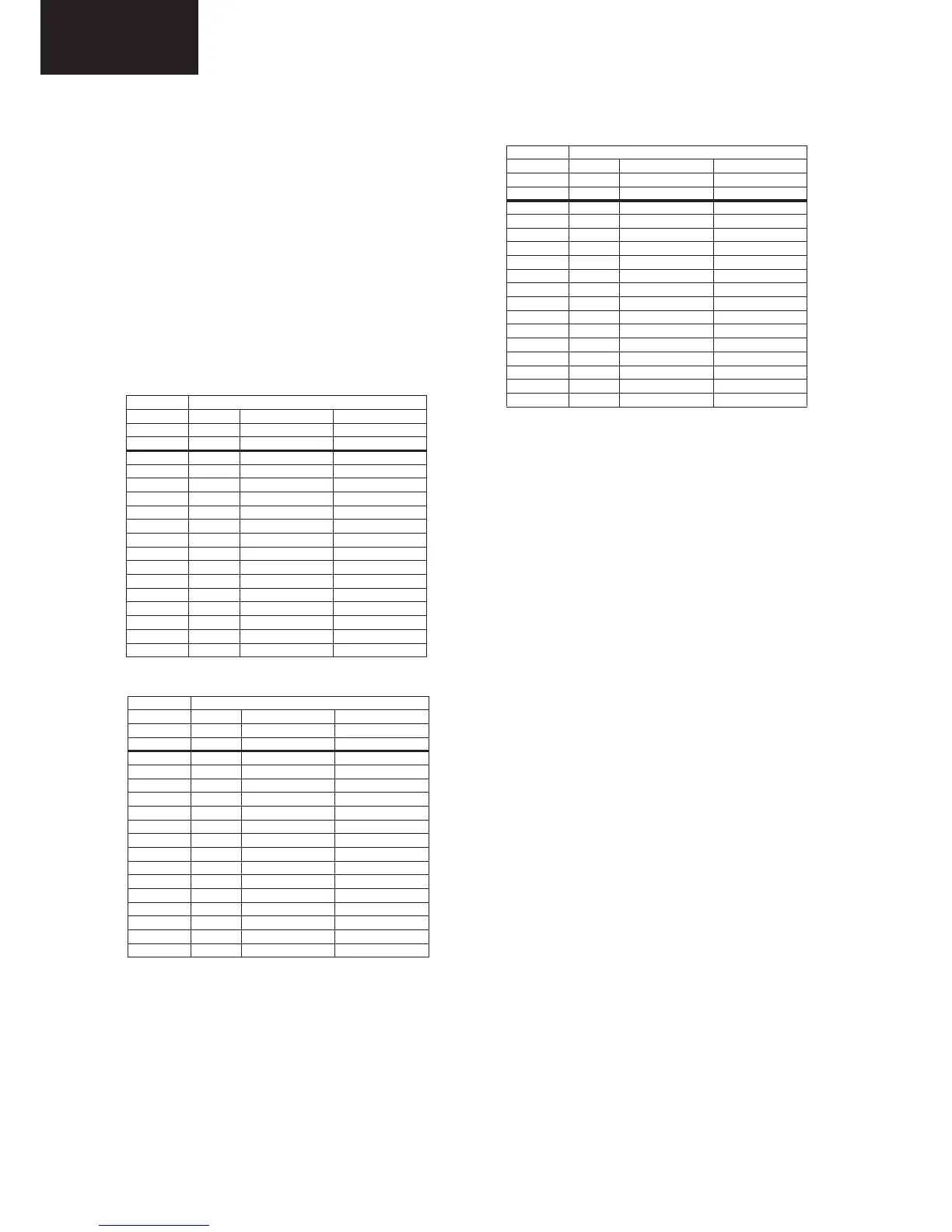
7.2.2 Connector overview (series xxLE63xE/RU)
Table 7-2 Connector overview 46” sets
Circuit Descriptions (continued)
Consult the Parts Listing at the end of this document for the
order codes of the boards
Table 7-3 Connector overview 40" sets
7.3 DC/DC Converters
The on-board DC/DC converters deliver the following voltages
(depending on set execution):
• +3V3-STANDBY, permanent voltage for the Stand-by
controller, LED/IR receiver and controls; connector 1M95
pin 1
• +12V, input from the power supply for TV550 common
(active mode); connector 1M95 pins 6, 7 and 8
• +24V, input from the power supply for DVB-S2 (in active
mode); connector 1M09 pins 1 and 2
• +1V1, core voltage supply for PNX855xx; has to be started
up first and switched "off" last (diagram B03B)
• +1V2, supply voltage for analogue blocks inside PNX855xx
• +1V8, supply voltage for DDR2 (diagram B03B)
• +2V5, supply voltage for analogue blocks inside PNX855xx
(see diagram B03E)
• +3V3, general supply voltage (diagram B03E)
• +5V, supply voltage for USB and CAM (diagram B03E)
• +5V-TUN, supply voltage for tuner (diagram B03E)
• +V-LNB, input voltage for LNB supply IC (item no. 7T50)
• +5V-DVBS, input intermediate supply voltage for DVB-S2
(diagram B08A)
• +3V3-DVBS, clean voltage for silicon tuner and DVB-S2
channel decoder
• +2V5-DVBS, clean voltage for DVB-S2 channel decoder
• +1V-DVBS, core voltage for DVB-S2 channel decoder.
A +12 V under-voltage detector (see diagram B03C) enables
the 12V to 3.3V and 12V to 5V DC/DC converters via the
ENABLE-3V3-5V line, and the 12V to 1.8V DC/DC converter
via the ENABLE-1V8 line. DETECT2 is the signal going to the
Stand-by microcontroller and ENABLE-3V3n is the signal
coming from the Stand-by microcontroller.
Diagram B03D contains the following linear stabilisers:
• +2V5 stabiliser, built around item no. 7UCO
• +5V-TUN stabiliser, built around items no. 7UA6 and 7UA7
• +1V2 stabiliser, built around items no. 7UA3 and 7UA4.
Diagram B08A contains the DVB-S2-related DC/DC
converters and -stabilisers:
• a +24V under-voltage detection circuitry is built around
item no. 7T04
• the switching frequency of the 24 to 14...20V switched
mode converter is 350 kHz (item no. 7T03 and +V-LNB
lines)
• the output signal on the +V-LNB line goes to the LNBH23Q
(item no. 7T50)
• the LNBH23Q (item no. 7T50) sends a feedback signal via
the V0-CNTRL line
Connector
no. 1308 1316 1M95
Descr. Mains to display to SSB
Pin CN1 CN2 CN4
1 N Anode 1+ +3V3stdby
2 L n.c. Standby
3 - Cathode 1- GND1
4 - n.c. GND1
5 - Anode 2+ +12V
6 - n.c. +12V
7 - Cathode 2- +Vsnd (+24V)
8 - n.c. GND_SND
9 - Anode 3+ BL-ON-OFF
10 - n.c. BL-DIM1 (Vsync)
11 - Cathode 3- BL-I-CTRL
12 - n.c. POK
13 - Anode 4+ +24V (AL2_DVBS)
14 - n.c. GND1
15 - Cathode 4- -
7.2 Power Supply
7.2.1 Power Supply Unit
All power supplies are a black box for Service. When defective,
a new board must be ordered and the defective one must be
returned, unless the main fuse of the board is broken. Always
replace a defective fuse with one with the correct
specifications! This part is available in the regular market.
Table 7-1 Connector overview 32" sets
Connector
no. 1308 1316 1M95
Descr. Mains to display to SSB
Pin CN1 CN2 CN4
1 N A2 +3V3SB
2 L n.c. Standby
3 - pin 5 GND1
4-n.c. GND1
5 - pin 3 +12V3
6 - n.c. +12V3
7-OCD +Vsnd
8-n.c. GND1
9 - A1 BL-ON-OFF
10 - n.c. BL-DIM1
11 - pin 13 BL-I-CTRL
12 - n.c. POK
13 - pin 11 +24V
14 - n.c. GND1
15 - GND1 -
In this manual, no detailed information is available because of
design protection issues.
 Loading...