R-3A53
R-3A53B
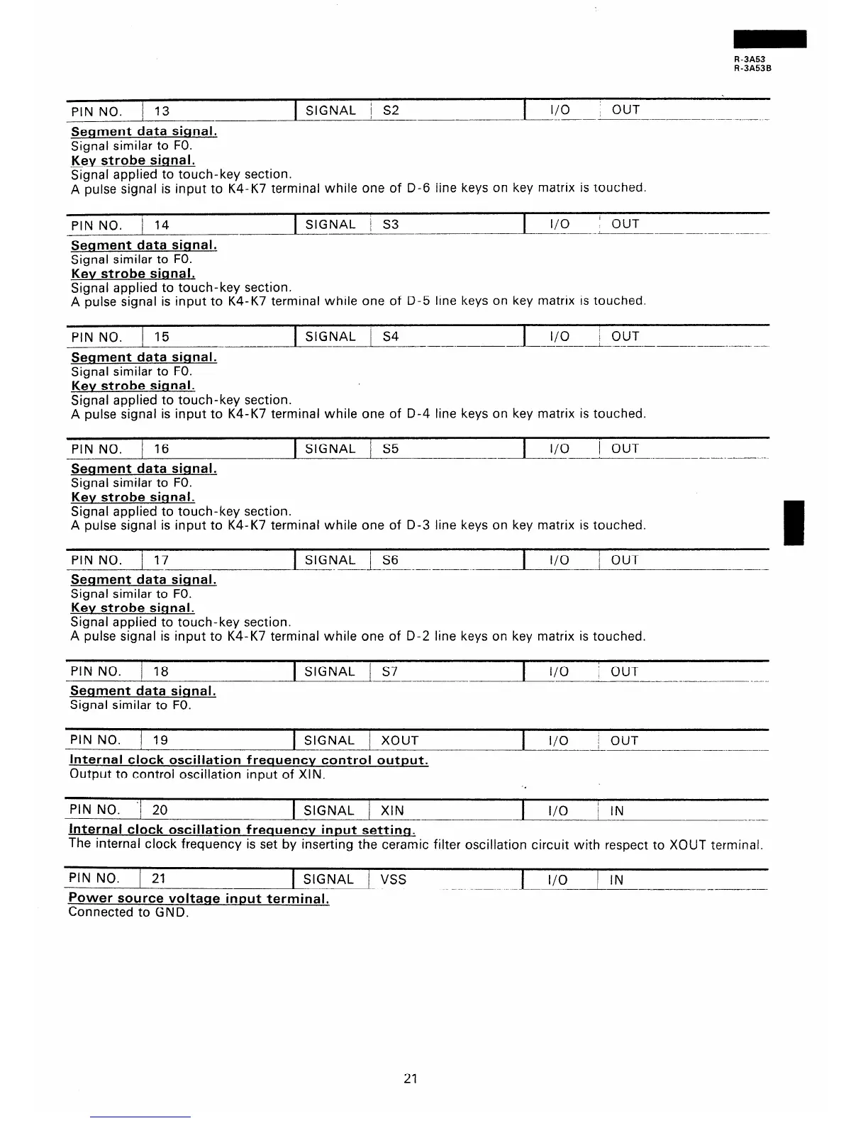
PIN NO. j 13
Segment data signal.
Signal similar to FO.
Key strobe sianal.
SIGNAL j S2
I/O ; OUT
~-____--
--- ---- ..-- - _____ _
Signal applied to touch-key section.
A pulse signal is input to K4-K7 terminal while one of D-6 line keys on key matrix is touched.
PIN NO. 1 14
SIGNAL / S3
I
I/O
’ OUT
----~
Segment data signal.
Signal similar to FO.
Key strobe signal.
Signal applied to touch-key section.
A pulse signal is input to K4-K7 terminal while one of D-5 line keys on key matrix is touched.
G-NO. 1 15
Segment data signal.
Signal similar to FO.
Key strobe signal.
1 SIGNAL i S4
-I-
I/O
; OUT
___---__- -____ ----
Signal applied to touch-key section.
A pulse signal is input to K4-K7 terminal while one of D-4 line keys on key matrix is touched.
PIN NO. / 16
1 SIGNAL j S5
--L-!E-OUT
___ .
Segment data signal.
Signal similar to FO.
Key strobe signal.
Signal applied to touch-key section.
A pulse signal is input to K4-K7 terminal while one of D-3 line keys on key matrix is touched.
I
PIN NO. 17 1 SIGNAL LS6
. __ _-___-_-- _
I
I/O
1 OUT
Segment data signal.
Signal similar to FO.
Key strobe sianal.
Signal applied to touch-key section.
A pulse signal is input to K4-K7 terminal while one of D-2 line keys on key matrix is touched.
PIN NO. / 18
1 SIGNAL j S7
I
l/O
: OUT
-__-__-___
____--
Seqment data signal.
Signal similar to FO.
PIN NO. 1 19
1 SIGNAL 1 XOUT
Internal clock oscillation frequency control output.
Output to control oscillation input of XIN.
I
I/O
i OUT
----A.--
___I___ -..- ___.-
PIN NO. ‘/ 20
1 SIGNAL 1 XIN
I I/O
i IN
Internal clock oscillation frequency input settins
The internal clock frequency is set by inserting the ceramic filter oscillation circuit with respect to XOUT terminal.
PIN NO. 1 21
1 SIGNAL / VSS
Power source voltane input terminal.
Connected to GND.
I
I/O
) IN
--- ___--
21
 Loading...