R-3A53
R-3A53B
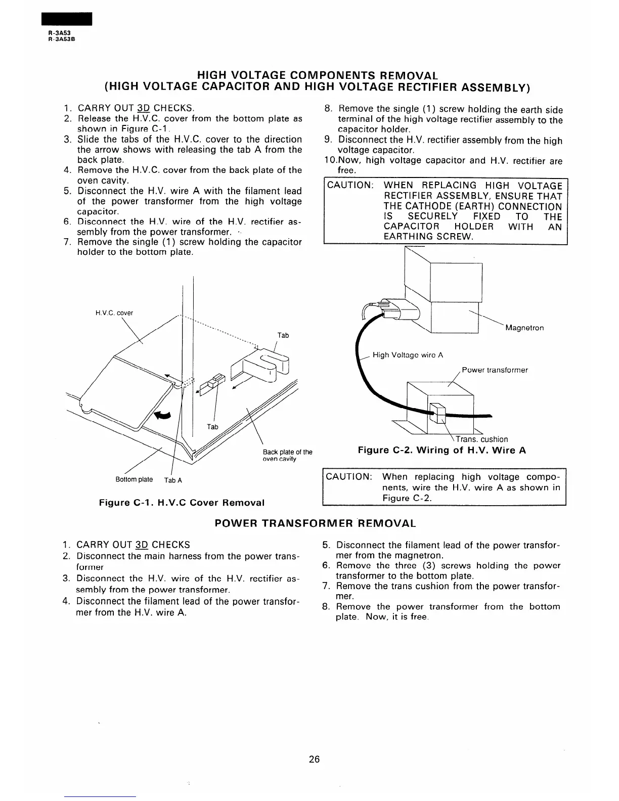
HIGH VOLTAGE COMPONENTS REMOVAL
(HIGH VOLTAGE CAPACITOR AND HIGH VOLTAGE RECTIFIER ASSEMBLY)
1. CARRY OUT 3iJ CHECKS.
2. Release the H.V.C. cover from the bottom plate as
shown in Figure C-l.
8. Remove the single (1) screw holding the earth side
terminal of the high voltage rectifier assembly to the
capacitor holder.
3. Slide the tabs of the H.V.C. cover to the direction
the arrow shows with releasing the tab A from the
back plate.
4. Remove the H.V.C. cover from the back plate of the
oven cavity.
5. Disconnect the H.V. wire A with the filament lead
of the power transformer from the high voltage
capacitor.
6. Disconnect the H.V. wire of the H.V. rectifier as-
sembly from the power transformer. p-
7. Remove the single (1) screw holding the capacitor
9. Disconnect the H.V. rectifier assembly from the high
voltage capacitor.
1 O.Now, high voltage capacitor and H.V. rectifier are
free.
CAUTION: WHEN REPLACING HIGH VOLTAGE
RECTIFIER ASSEMBLY, ENSURE THAT
THE CATHODE (EARTH) CONNECTION
IS
SECURELY FI)(ED TO
THE
CAPACITOR
HOLDER
WITH AN
EARTHING SCREW.
holder to the bottom plate.
Bottom plate
Tab A
Figure C-l. H.V.C Cover Removal
High Voltage wire A
ower transformer
Figure C-Z. Wiring of H.V. Wire A
CAUTION: When replacing high voltage compo-
nents, wire the H.V. wire A as shown in
Figure C-2.
POWER TRANSFORMER .REMOVAL
1. CARRY OUT3JCHECKS
2. Disconnect the main harness from the power trans-
former
3. Disconnect the H.V. wire of the H.V. rectifier as-
sembly from the power transformer.
4. Disconnect the filament lead of the power transfor-
mer from the H.V. wire A.
5. Disconnect the filament lead of the power transfor-
mer from the magnetron.
6. Remove the three (3) screws holding the power
transformer to the bottom plate.
7. Remove the trans cushion from the power transfor-
mer.
8. Remove the power transformer from the bottom
plate. Now, it is free.
26
 Loading...