7. PARAMETER SETTING VM-5S
-55-
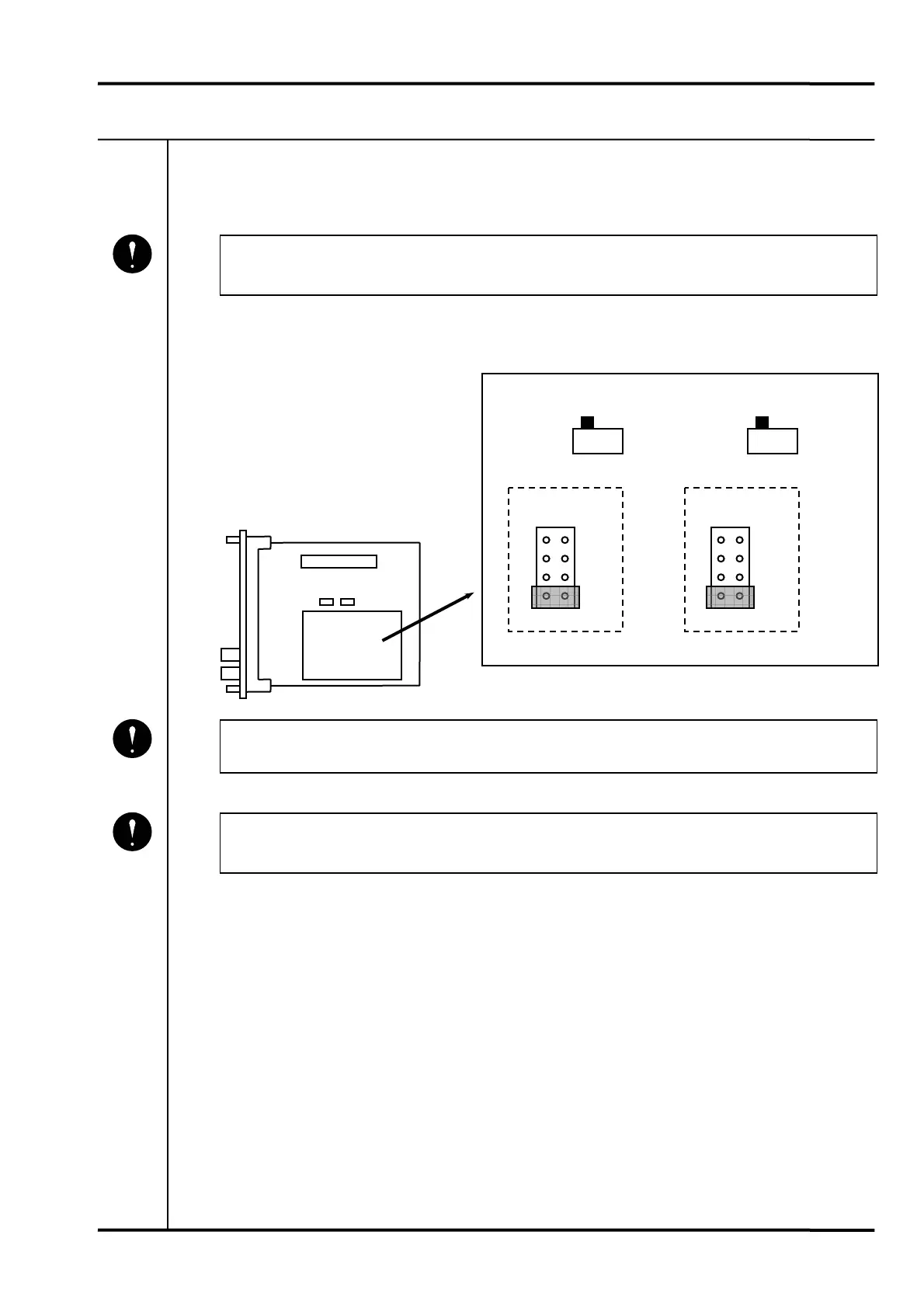
7-12 HYSTERESIS SETTING
(1) Remove the monitor unit from the rack.
• Refer to the instruction manual of the instrument rack in which the monitor is
installed.
(2) The jumper pins for hysteresis setting are located on the trigger card on the main board.
Connect the jumper in the desired position (marked 0.1V, 0.2V, 0.5V and 1.0V).
• Do not touch any parts not specifically mentioned.
(3) After verifying the set value, reinstall the monitor unit in the rack.
• Refer to the instruction manual of the instrument rack in which the monitor is
installed.
Mandatory
VM-5 TRIGGER CARD
J1
CH1
HYS. SET
0.1V
0.2V
0.5V
1.0V
VM-5
TRIGGER
CARD
J3
CH2
HYS. SET
0.1V
0.2V
0.5V
1.0V
CH2 TRG. MODE
AUTO MAN.
CH1 TRG. MODE
AUTO MAN.
S1
S2
Mandatory
Mandatory
 Loading...