NOTE
When using a particle filter, the measurement result is delayed by one cycle scan due to
the additional calculation steps.
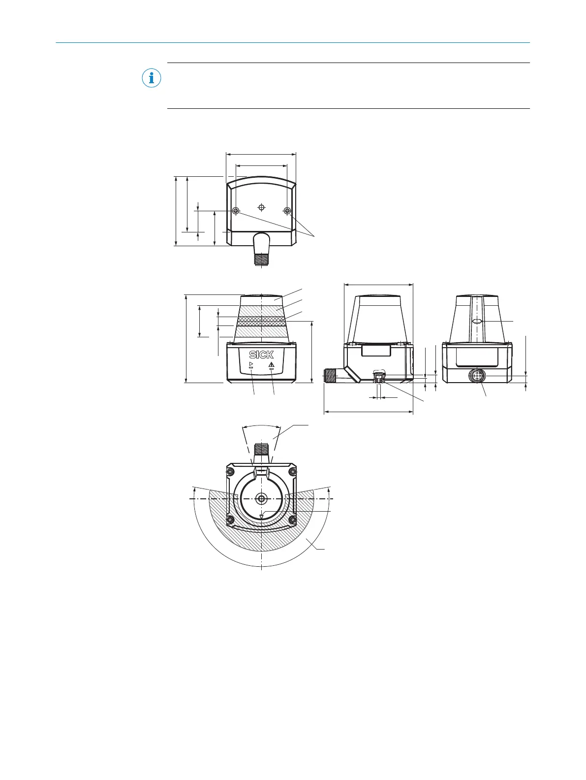
3.3 Setup and dimensions
3
4
2
5
8
7
‒100°
90°
–90°
0°
à
ß
1
9
44.4 (
1.75)
47.7 (
1.88
)
18.1
(
0.71
)
75.8
(2.98)
27.3
(
1.07
)
8 (
0.31
)
53 (
2.09
)
Repair warranty
void if broken
59.6 (
2.35
)
7 (
0.28
)
76.6 (
3.02
)
M3
4 (
0.16
)
6.2 (
0.24
)
1
2
3
4
5
30°
200°
100°
1
6
30
(
1.18
)
59.6 (
2.35
)
60 (
2.36
)
Figure 2: Setup and dimensions TiM1xx
1
M3 threaded mounting hole, 2.8mm deep (blind hole thread), tightening torque 0.7Nm
2
Optics cover
3
Receiving range (light inlet)
4
Transmission range (light emission)
5
Green LED
6
Red LED
7
Marking for the position of the light emission level
8
5-pin M12 male connector, rotatable
9
Area in which no reflective surfaces are permitted when the device is mounted
ß
Bearing marking to support alignment (0° axis)
3 PRODUCT DESCRIPTION
12
O P E R A T I N G I N S T R U C T I O N S | TiM1xx 8020631/1DWW/2022-08 | SICK
Subject to change without notice

 Loading...