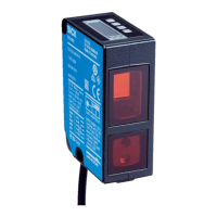
Electrical block diagrams
SOPASSOPAS
„USB 2.0“
USBUSB
TiM1xx
„DC 24 V“
SiLink2
Master
Figure 6: Electrical block diagram for configuration with SiLink2 Master
Figure 7: Electrical block diagram for configuration and operation with IO-Link Master
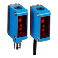
NOTICE
If the max. current of the IO-Link Master is not limited to 1A: Protect the device with an
external 0.8A slow-blow fuse.
TiM1xx
Connection box
V
s
customer-
provided
delay-
action
fuse
0.8A/T
Figure 8: Electrical block diagram for operation with direct connection
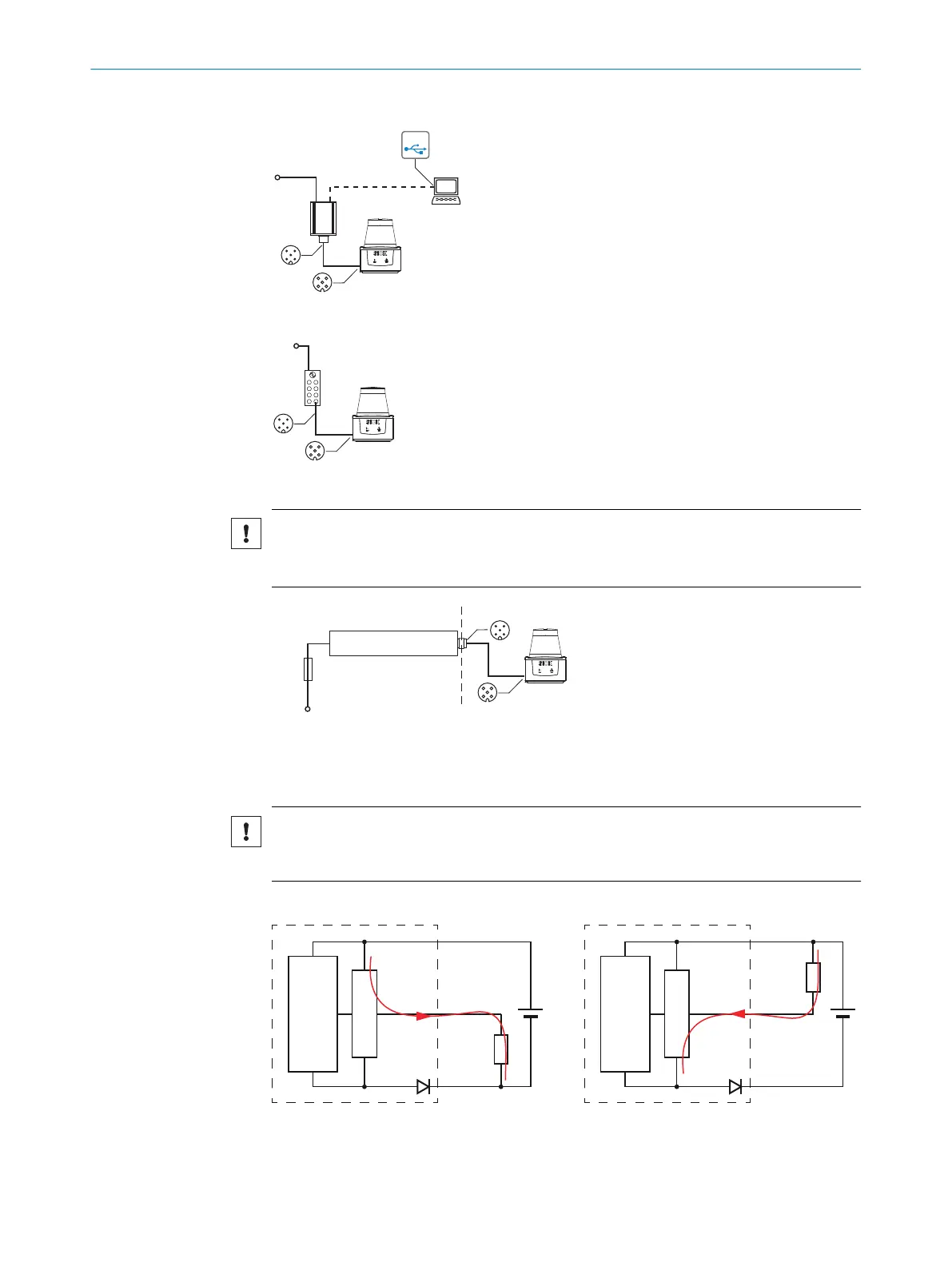
Digital output PNP or NPN
NOTICE
With NPN wiring, the digital output is already activated during the device initialization
phase.
Figure 9: Connection example digital output
ELECTRICAL INSTALLATION 6
8020631/1DWW/2022-08 | SICK O P E R A T I N G I N S T R U C T I O N S | TiM1xx
19
Subject to change without notice

 Loading...