24
SP 75 T / SP 95 T / SP 125 T 2.0 - 2002
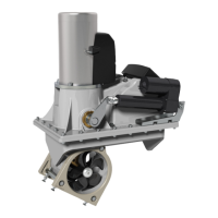
1. Um genügend Öldruck im Getriebegehäuse zu gewährleisten,
muß der Vorratsbehälter für das Getriebeöl oberhalb der
Wasserlinie montiert sein. Der Abstand muß hierbei mind. 20%
der Distanz von Wasserline zum Zentrum des Tunnels sein.
2. Den Schlauch für das Öl am Vorratsbehälter und am vorge-
sehenen Nippel der Motorhalterung befestigen. Die beiden
Schlauchklemmen anziehen. Sicherstellen, daß das Öl unge-
hindert und direkt in das Getriebegehäuse fließen kann.
3. Den Vorratsbehälter mit Getriebeöl EP90 füllen.
4. Wenn das Getriebegehäuse nicht schon vorher befüllt wurde,
die Ölablaßschraube (6) öffnen, bis Öl austritt, dann sicher
festziehen. Immer die Kupferdichtung (7) verwenden.
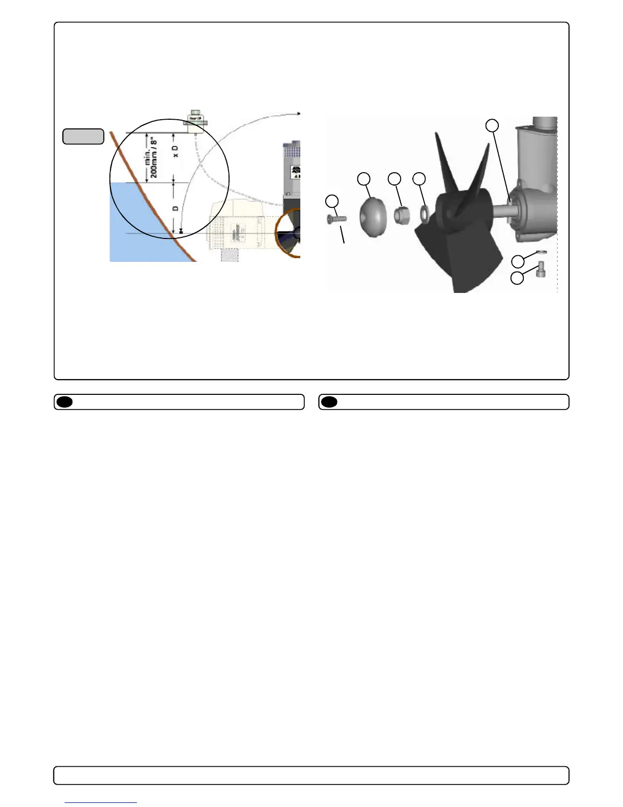
5. Die Propellerachse so drehen, daß der Mitnahmestift (5) in
horizontaler, zentrierter Position steht.
6 Den Propeller auf die Achse stecken und bis zum Anschlag
schieben. Die Aussparung für den Mitnahmestift muß eben-
falls in horizontaler Position stehen. Zwischen Propellernabe
und Getriebegehäuse darf kein Abstand sein.
7. Befestigungsschraube (3) inkl. Scheibe (4) bis zum Anschlag
anziehen.
8. Die Zinkanode (2) mit der Befestigungsschraube (1) anbrin-
gen. Locktite o.ä. verwenden, damit sich die Schraube durch
die Rotation des Propellers nicht löst.
Teile:
1 : Schraube für Zinkanode 5 : Mitnahmestift
2 : Zinkanode 6 : Ölablaßcschraube
3 : Propellermutter 7 : Kupferscheibe / Dichtung
4 : Scheibe
Ölvorratsbehälter & Propeller
D
5
6
32
1
4
7
Locktite
1. Fit the oil tank above the waterline by atleast 20% of the
distance from the waterline to the centre of the tunnel. This is
for ensuring enough overpressure of oil in the gearhouse.
2. Fit the oil tube to the tank and the feed pipe in the motor
bracket. Tighten the two tube clamp screws. Make sure that the
oil-tube has no loops that makes an airlock to stop the oil flow
and has a good angle to allow the oil to flow freely into the
gearhouse.
3. Fill the oil tank with gear oil type EP90.
4. If you did not prefill the gearhouse, open the oil drain screw (6)
until oil comes through, then tighten it securely and make sure
that the copper gasket (7) is present.
5. Turn the propeller shaft so that the drivepin (5) is in a horizontal
position and ensure that it is centred in the propellershaft.
6. Push the propeller onto the shaft with the track for the drivepin
in an horizontal position (same direction as you set the
drivepin), all the way in. There should be almost no gap
between the propeller hub and the gearhouse.
7. Place the washer (4) on the prop.shaft and then tighten the
lock-nut (3) on the propeller shaft.
8. Place the zinkanode (2) in its designated position and tighten
the zincanodes holding screw (1). Apply a thread glue (Locktite
or similar) to ensure that the zincanodes holding screw does
not un-screw itself from the propellers rotation.
Parts description:
1 : Screw for zincanode 5 : Drivepin for propeller
2 : Zincanode 6 : Oil drain screw
3 : Propeller lock nut 7 : Copper washer/seal for
4 : Washer oil drain screw
Fitting oil tank & propeller(s)
GB
Fig. 1
0,2

 Loading...