26
SP 75 T / SP 95 T / SP 125 T 2.0 - 2002
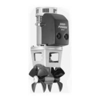
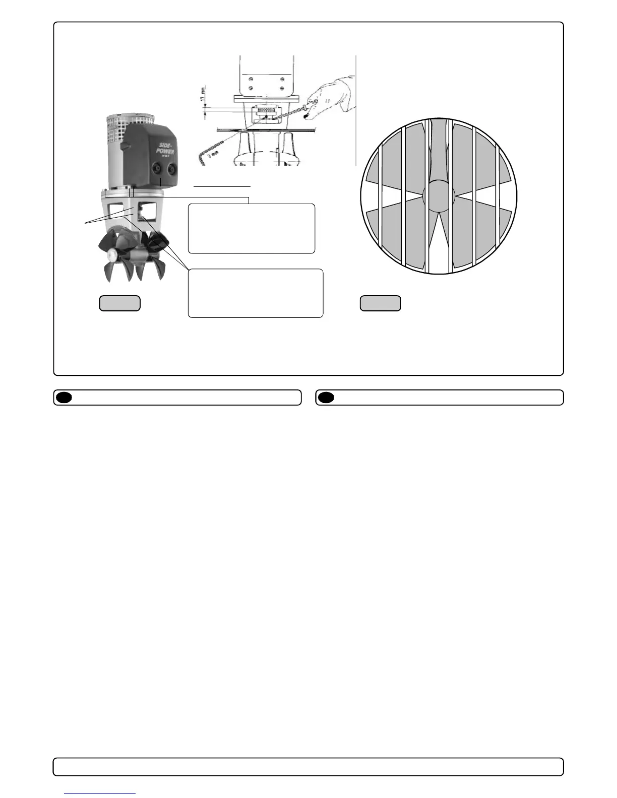
1. Die 4 Bolzen in der Motorhalterung enfernen.
2. Den unteren Teil der elastischen Kupplung montieren, beide Be-
festigungsschrauben festziehen und den Gummiring in einsetzen.
3. Den Motor vorsichtig auf die Motorhalterung aufsetzen.
Den Motor so plazieren, daß die Leitungsanschlüsse für die
spätere elektrische Installation zugänglich sind.
4. Mit den 4 Bolzen Motor und Motorhalterung verschrauben.
5. Wird der Motor mehr als 30
o
außerhalb der Vertikalen einge-
baut, so muß er ausreichend abgestützt werden. Siehe dazu
die Illustration in den Maßzeichnungen.
6. Die Befestigungsschrauben im unteren Teil der elastischen
Kupplung lösen. Den Gummiring ganz in den unteren Teil der
elastischen Kupplung einschieben und zusammen in den obe-
ren Teil der elastischen Kupplung schieben. Der Gummiring
muß vollkommen im oberen Teil sitzen, darf aber nicht zusam-
men gequetscht sein (17 mm). Den unteren Teil mit den bei-
den Befestigungsschrauben in neuer Position festschrauben.
7. Durch das Metallgitter am oberen Motorende prüfen, ob die
Federn für die Bürsten korrekt sitzen.
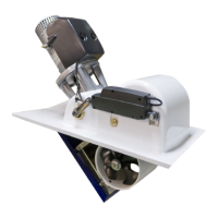
In manchen Fällen, z.B. bei flachem Rumpf oder im gerwerblichen
Einsatz (z.B. Fischfang) empfehlen wir, den Propeller durch ein Git-
ter vor der Tunnelöffnung zu schützen (Fig. 2). Dieses sollte auf ein
Minimum beschränkt und so stromlinienförmig wie möglich sein,
da die ansonsten die Leistung des Thrusters reduziert wird.
NB ! Wir empfehlen, auf das Getriebegehäuse Anti-Fouling
aufzutragen. Nicht auf die Propellerachse, Zinkanoden oder den
Verschluß des Getriebegehäuses auftragen.
NB ! Den Thruster nur für den Bruchteil einer Sekunde betätigen
wenn dieser nicht im Wasser ist.
NB ! Wird der Elektromotor eingebaut, falls das Boot noch in Bau
ist, so muß dieser abgedeckt werden, um eine Verschmutzung
von Relais und Motor zu verhindern. Diese Abdeckung muß vor
Benutzung des Thrusters entfernt werden.
Fig. 1 Fig. 2
1. Remove the 4 bolts in the motorbracket.
2. Mount the lower part of the flexible coupling and tighten the two
set screws. Insert the "rubber ring" in this lower part.
3. Place the motor gently on the motorbracket. Be careful, the
motor is heavy! Ensure that the "rubber ring" goes into position.
Ensure that you are placing the motor so that the cable
terminals on it are available for electric installation later.
4. Fasten the motor to the bracket with the 4 bolts and tigthen them.
5. If you are installing the motor in an angle of more than 30
o
off a
vertical position, the electromotor needs a separate/additional
support. See illustration in the measurements drawings.
6. Lift the lower part of the flexible coupling together with the
rubber ring into the upper flexible coupling. The rubber ring
must be in its correct position in the upper part, fully inserted
but not com-pressed against it (17 mm). Secure the lower part
of the flexible coupling in its new position by tightening the two
set-screws.
7. Check if the springs for the brushes sit correctly on the brushes
(see through the metal web around the top of the electromotor).
In some cases (shallow installation or workboat / fishingboat
only) we recommend to protect the propeller by mounting a grid in
the tunnel opening (Fig. 2). It is important to keep a grid to a
minimum and as streamlined for the thrusters waterflow as
possible, as it will decrease the effect of the thruster.
NB ! Paint the gearhouse and propeller with antifouling for
propellers to prevent growth of barnacles or similar which would
reduce the performance dramatically. Do not paint the propeller
shaft, the zincanodes or the end face of the gearhouse.
NB! Do not run the thruster for more than very short bursts
without being in the water.
NB ! If the boat is still being built when the electromotor is in-
stalled, it must be covered up to avoid dust from the building
going into the motor and the solenoids. This cover must be
removed before the thruster is being used.
17mm
Bolt tightening force (4x):
SP 75/95 T: 33 Nm (24 lb/ft)
SP 125 T: 33 Nm (24 lb/ft)
Bolt tightening force (2x):
SP 75/95 T: 17 Nm (12,4 lb/ft)
SP 125 T: 33 Nm (24 lb/ft)
Einbau des Elektromotors
D
Fitting the electromotor
GB

 Loading...