28
SP 75 T / SP 95 T / SP 125 T 2.0 - 2002
• Übersicht:
- Leitungslängen beziehen sich auf die Gesamtlänge von + und -
- Batterieangabe ist min. Kaltstartkapazität, nicht Ah.
- Sicherung: träge Ausführung; angeg. Stomverbrauch min. 5 Min.
* Kabel- und Batteriegröße, falls eine zusätzliche Batterie, mit min.
der Kaltstartkapazität (mit A angegeben), im Bug installiert ist.
• Da die am laufenden Motor anliegende Spannung die Umdre-
hungszahl und damit die Leistungskraft bestimmt, sind Kabel mit
ausreichendem Querschnitt und Batterien mit hoher Strom-
kapazität zu verwenden. Bitte die unten angegebenen Mindest-
größen für Kabelquerschnitt und Batterien berücksichtigen.
Natürlich können für noch bessere Leistung überdimensionierte
Bauteile verwendet werden.
• Auf der positiver Hauptseite muß ein Hauptschalter (*C) mon-tiert
werden, der die Leistung ohne größeren Spannungsverlust
weiterleitet. Damit kann die Spannung für den Thruster in Not-
fällen abgeschaltet werden, ohne die übrige Bordelektrik zu be-
einflussen. Dieser sollte an einer leicht zugänglichen Stelle pla-ziert
sein und die Anleitung darauf hinweisen, daß dieser wie die andere
Bordelektrik bei Nichtbetrieb abgeschaltet werden sollte.
• Zum Schutz gegen Kurzschlüsse empfehlen wir, in der positiven
Leitung eine Sicherung (*D) zu installieren. Es sollte eine
Qualitätssicherung von ausreichender Größe verwendet werden.
Die Sicherung sollte in "träger" Ausführung sein und die
angegebene Amperezahl mindestens 5 Minuten aushalten.
• Statt Sicherung und Hauptschalter kann ein Sicherungsautomat
verwendet werden, falls die gleiche Funktionalität gewährleistet ist.
• Die Leitungsenden müssen so mit Kabelschuhen versehen und
isoliert sein, daß sie nur mit dem Terminal Verbindung haben.
• Die Kabelschuhe müssen korrekt angezogen werden. Die innere
Mutter sichern (Fig. 2). Anzugsmoment max. 15 Nm / 11 lb/ft.
Das Minus-Kabel (Negativ) (*A) am A1 (-) Terminal anschließen.
Das Plus-Kabel (Positiv) (*B) am "+" Terminal anschließen
SP 75/95/125: ø10mm Bolzen. Anzugsmoment: 15 Nm / 11 lb/ft.
Elektrische Installation
D
• Explanation of electrical table
- All cable lengths are the total of + and - (to and from).
- Battery size is stated as minimum cold crank capacity, not Ah.
- Use slow fuse rated to hold stated Amp-Draw for min. 5 minutes.
* Cable size and main battery size when an extra bow battery
with minimum the CCA mentioned as A is installed.
• It is important that you use a good cable size and batteries with
a high cranking capacity to feed the thruster, because it is the
actual voltage at the motor while running the thruster that decides
the output rpm of the motor and thereby the actual thrust. Please
see the list below for advised min. sizes of cables and batteries.
You can of course use larger cables for even better results.
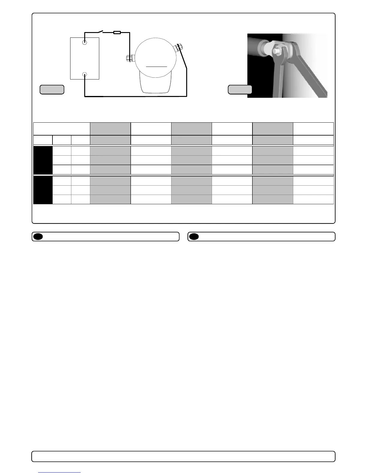
• A main switch (*C) that can take the load without noticable
voltage drop must be installed in the main positive lead so the
power for the thruster can be turned off independent of the rest
when not on board or in emergencies. This should be placed in
an easy accessible place and the boats instructions should inform
that this should be turned off like the boat's other main switches.
• We also advice to install a fuse (*D) in the positive lead for
protection agains short circuiting of the main cables. This fuse
should be of a adequate quality which normally means that it is
physically large as these have less voltage drop than the simple /
small ones. It should be of the slow type and sized to take the
amperage draw for atleast 5 minutes.
• A circuit breaker can be used instead of the fuse and main power
switch as long as the functionality is the same.
• The cable ends must be fitted with terminals and these must be
well isolated against contact with anything but the proper
connection point.
• Terminals must be properly tightened. Secure/hold inner nut
when tightening (Fig. 2). Tighten with max: 15 Nm / 11 lb/ft.
The negative / minus cable (*A) connects to the A1 (-) terminal.
The positive / plus cable (*B) connects to the "+" terminal.
SP 75/95/125: ø10mm / 3/8" bolt. Tighten with 15 Nm / 11 lb/ft.
Electrical installation
GB
Battery
12V or 24V
+
-
M
-
+
*D
*C
SP 75 T
SP 75 T
SP 125 T
Fig. 1 Fig. 2
50 mm2 95 mm2 120 mm2 150 mm2 N / A N / A
O OOO+ OOOO+ 2xOOO
N / A 50 mm2 70 mm2 95 mm2 120 mm2 150 mm2
O OO+ OOO+ OOOO+ 2xOOO
35 mm2 35 mm2 50 mm2 70 mm2 95 mm2 120 mm2
2 2 O OO+ OOO+ OOOO+
70 mm2 105 mm2 150 mm2 175 mm2 N / A N / A
OO+ OOOO 2xOOO 2xOOOO
N / A 70 mm2 95 mm2 120 mm2 150 mm2 180 mm2
OO+ OOO+ OOOO+ 2xOOO 2xOOOO
50 mm2 50 mm2 70 mm2 95 mm2 120 mm2 150 mm2
O O OO+ OOO+ OOOO+ 2xOOO

 Loading...