4 Wiring
4.1 Wiring overview
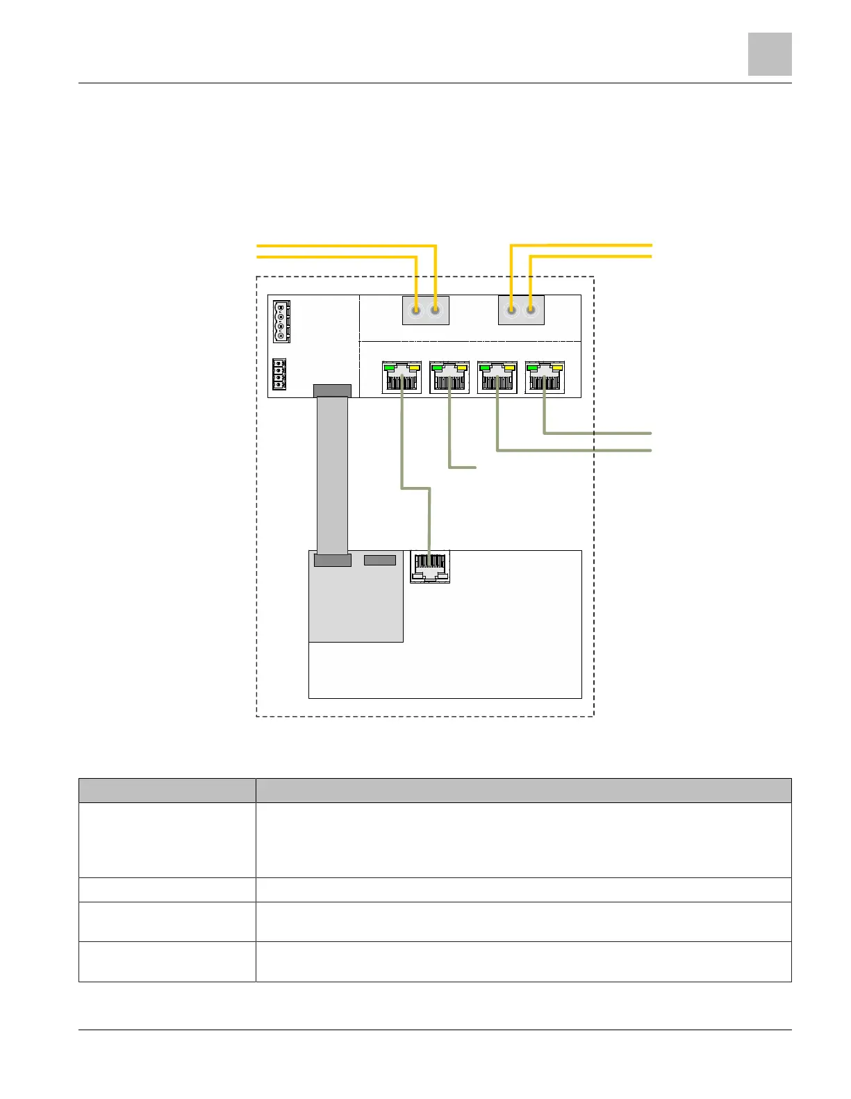
The figure shows a typical application of the Ethernet switch built into an FS20 panel
as well as all connections. The example shows the wiring of a panel in an optical
Ethernet ring.
P5 P4
P3 P2
P0
P1
POWER
FAULT
MoNet
Ethernet Ring
MoNet
PMI & Mainboard
Ethernet
FCA2031
Panel
2x Ethernet internal
2x Ethernet external
MoNetBus
X
Figure 7: Wiring of the Ethernet switch (modular) FN2012
All of the connections shown are current-limited and supervised.
Connector/Designation Description
P0, P1 For FS20/FS920 applications: Optional modules for Ethernet ring connections for
electrical or fiber-optic wiring (TP, SM, MM)
For XLS applications: Optional modules for Ethernet ring connections for optical
wiring only (SM/MM)
P4, P5 Panel-internal Ethernet connections
P2, P3 External Ethernet connections, e.g., for Desigo Fire Safety Works, MMS, Desigo Fire
Safety View
MoNet Connection from the PMI & mainboard to the Ethernet switch (modular) for the supply
and transmission of the degraded mode and system signals (MoNetBus)
Wiring
Wiring overview
4
A6V10407862_e_en_-- 13 | 32
 Loading...