4.3 General wiring XLS
J11
P4/P5
local Ethernet
TB4
non power limited
DC 24 V OUT
POWER
A+, A-
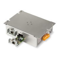
Figure 9: Wiring overview of XLS components
● The Ethernet switch (modular) is supplied via the PSC-12 power supply,
connection TB4.
● The internal Ethernet connection is established between port4 or port5 on the
Ethernet switch (modular) and the PMI-2, connection J11.
4.4 MoNet bus connection
Preparing the Ethernet switch (modular) for MoNet bus connection
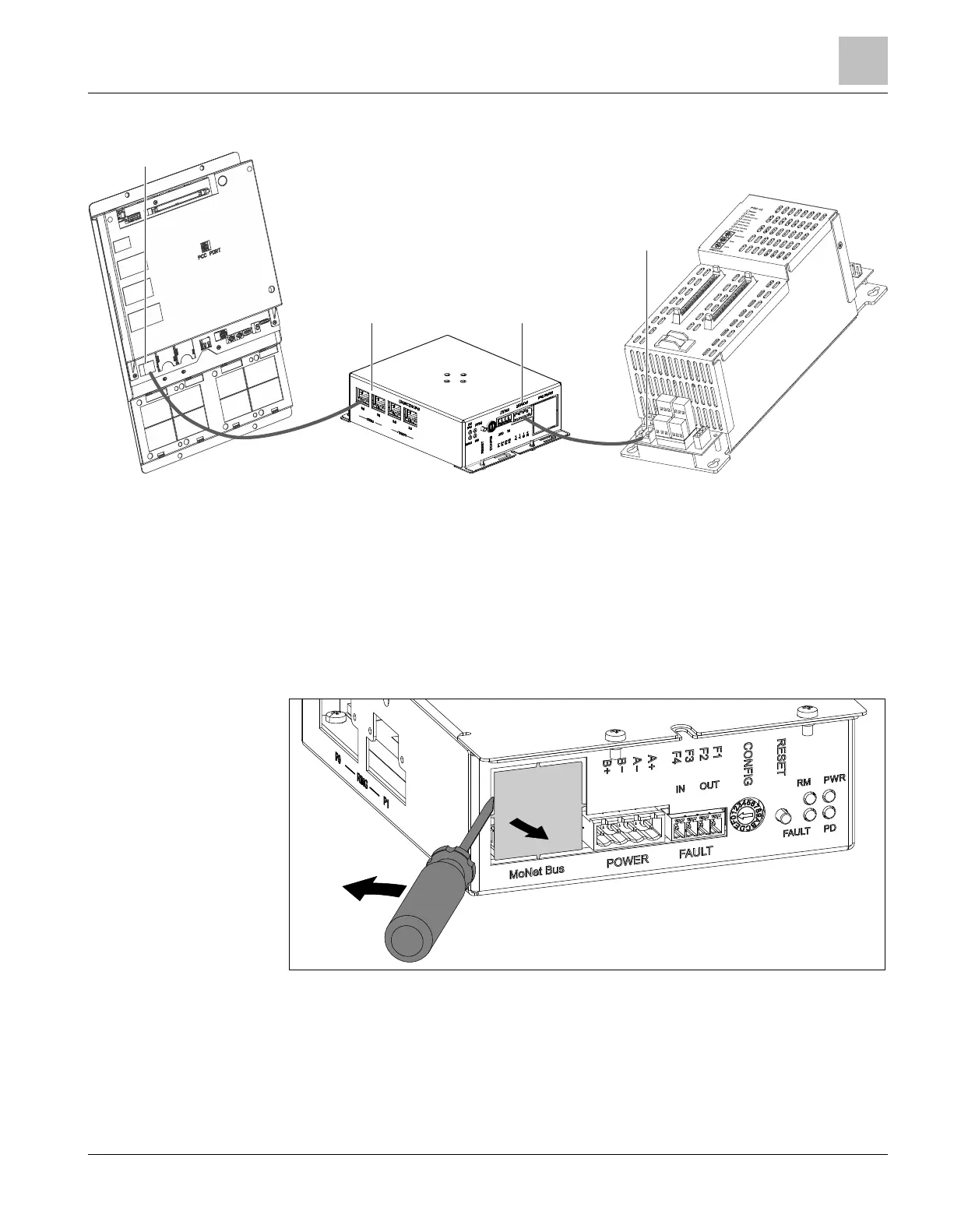
Figure 10: Breaking out the MoNet bus cover plate
l Use a screwdriver to carefully remove the cover plate for the MoNet connector as
shown in the illustration.
a Levering the screwdriver in the direction shown by the arrow causes the cover
plate to come loose at the four predetermined breaking points.
Wiring
General wiring XLS
4
A6V10407862_e_en_-- 15 | 32
 Loading...