5
MECHANICAL INSTALLATION .......................................
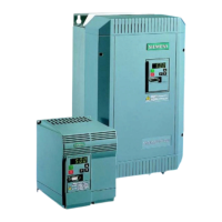
MOUNTING
The IP20/21 range of Eco units can be
mounted side-by-side without space in
between. A clearance distance of at least
100mm top and 160 mm bottom must be left
free for the movement of cooling air.
IP56 Eco units must have a clearance distance
of at least 150mm in all directions.
A good bonding between the Eco and the
metal back plate is necessary to ensure good
grounding and low RF (radio frequency)
impedance. If necessary remove some back
plate paint and/or use toothed washers to
ensure safety and EMC (electro-magnetic
compatibility). Use an earth braid on 400V
ratings 1.5KW and below.
Ambient temperature
MICROMASTER Eco 0
o
C to 50
o
C.
MIDIMASTER Eco (IP20/21/56) 0
o
C to 40
o
C.
Ensure that the Eco is not subject to shock,
vibration or atmospheric pollutants.
MOTOR CABLES
To minimise the effects of radio frequency
emissions:-
• Screened cables should be used between
the Eco and the motor.
• Keep cables to motor as short as possible,
generally under 25m.
• Terminate cable screens correctly (use
gland fittings which give 360 deg.
conduction) on both the Eco gland plate and
the motor terminal box.
• Fit suppressors on all contactor coils.
• If an external input EMC filter is to be fitted
then ensure that it is positioned as close as
possible to the Eco and is well grounded to
the metal back plate. Use screened cable
between the external input EMC filter and
the Eco input terminals, and ground cable
screen correctly.
All MICRO/MIDIMASTER Eco products comply
with the requirements of the EMC Directive
when installed in accordance with the wiring
recommendations of this manual. The units
comply with European Norm EN61800-3
“Adjustable speed electrical power drive
systems”. This standard specifies different
limits for domestic and industrial applications,
which defines whether an integral EMC filter is
required. For further information refer to the
Eco Reference Manual.
When units are selected which include integral
filters they will meet the conducted and
radiated RF emissions limits specified in EN
55011.
CONTROL AND SERIAL
COMMUNICATION CABLES
To minimise the effects of radio frequency
emissions and interference:-
• Screened control and data cables should be
used with the Eco.
• Terminate the control and data cable
screens correctly on the Eco by using the
gland plate and/or clamps provided.
Consult the instructions for the Building
Management System or controller at the
opposite cable end.
• IT IS MOST IMPORTANT THAT THE
MOTOR AND CONTROL CABLES ARE
KEPT APART. IF CONTROL AND
POWER CABLES NEED TO CROSS,
ARRANGE THE CABLES SO THAT THEY
CROSS AT 90° IF POSSIBLE.
CIRCULATING CURRENTS
If there is a slight difference between the
chassis potential of the Eco and the Building
Management System (or controller) then
circulating currents can occur in the control or
data cable screens.
These circulating currents should be avoided
by separately connecting the chassis of both
pieces of equipment securely to the same
earthing point.
 Loading...