6
ELECTRICAL INSTALLATION.........................................
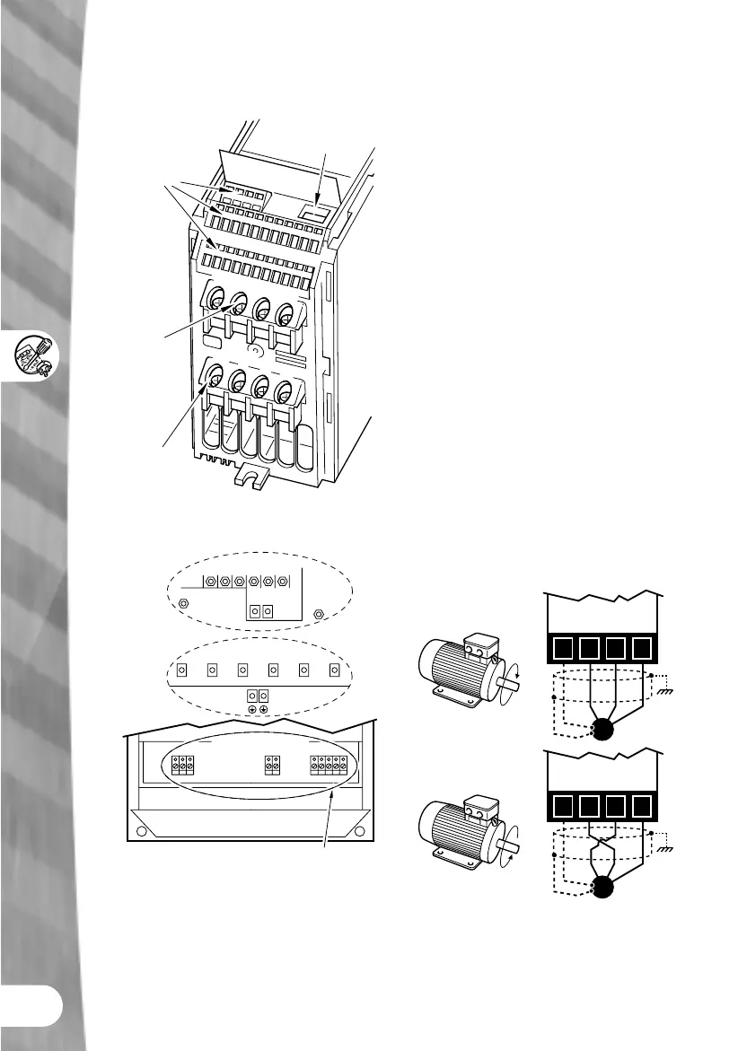
PE
L/L1
N/L2
L3
PE
U
V
W
Motor
Terminals
DIP
Switch's
Control
Terminals
Input
Supply
Terminals
MICROMASTER Eco - Mains supply, motor
and control connections
DC-DC+
UVW
L1 L2 L3
FS4/5 units
Power and Motor terminals
PE PE
L1 L2 L3 U V W
DC- DC+
PE
PE
FS7 units
FS6 units
L1 L2 L3 U V W
MIDIMASTER Eco - Power and motor
connections.
Make sure that the Eco is securely mounted.
For 110kW to 315kW units the mains supply
terminals are at the top, and the motor
connection terminals are at the bottom.
CONNECTING TO MAINS
Terminals L/L1, N/L2 & L3
Ensure that the nameplate voltage of the Eco
(and the motor) corresponds to the mains
supply voltage to be used.
Check that the supply circuit protection is
correctly rated for the Eco nameplate input
current.
Ensure that all power cables are adequately
rated for the expected duty.
CONNECTING TO MOTOR
Terminals U, V, & W
Only use the Eco with fan or pump motors
(variable torque).
DIRECTION OF ROTATION
The direction of rotation of the motor can be
reversed by changing over two of the output
connections on the Eco.
xxxx
xxxx
UVWPE
UVWPE
M
M
NOTE
The power cable screen and control wiring
screen must be connected to the inverter gland
plate.
 Loading...