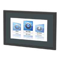
Mount the Climatix touch panel
4
14 | 30
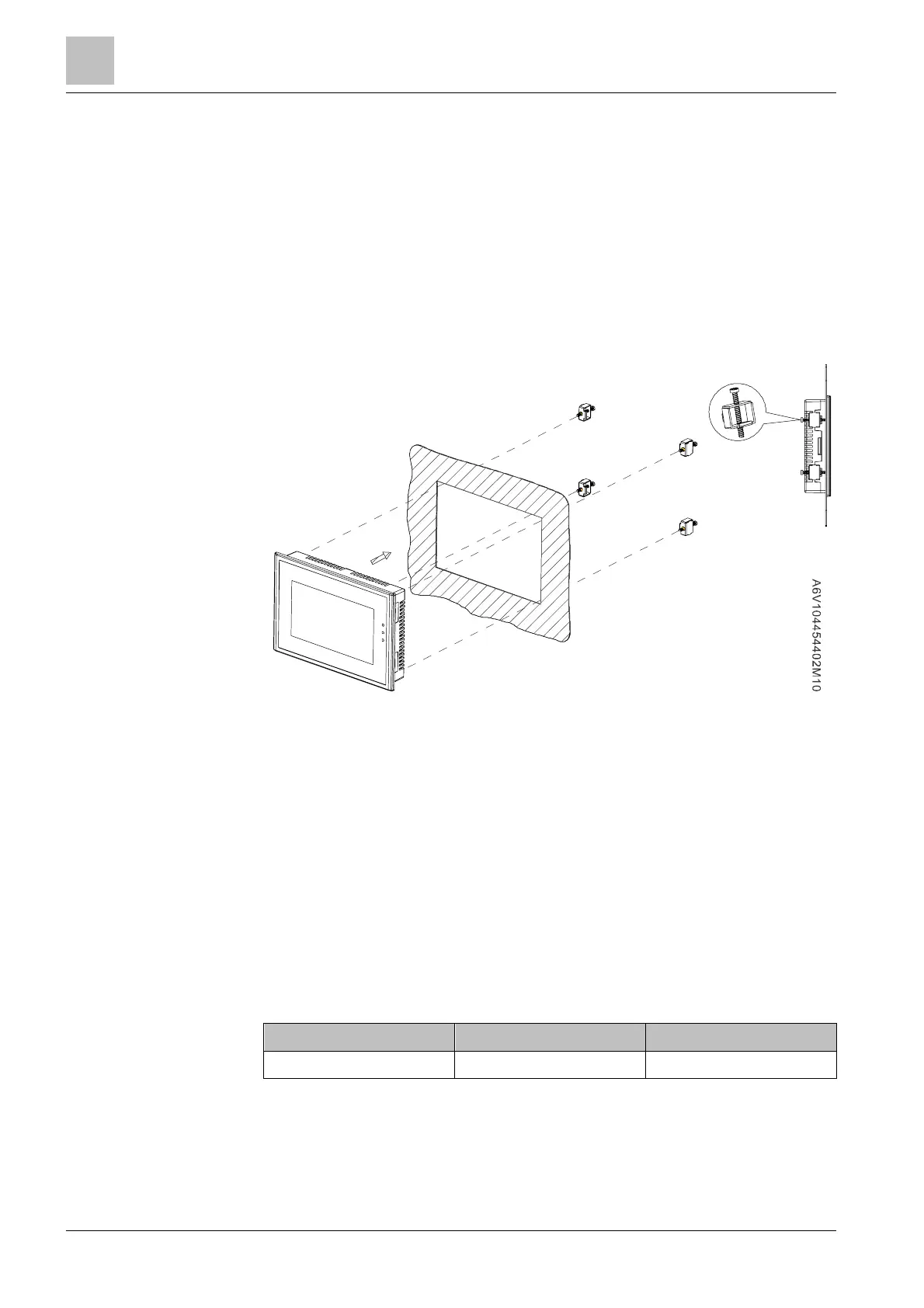
4.2 Mount the Climatix touch panel
● The material in the area of the mounting cutout must be sufficiently strong to
ensure lasting and safe mounting of the Climatix touch panel.
● The force of the mounting clips or device operation of the device may not
cause the material to become deformed.
1. Insert the Climatix touch panel through the mounting cutout from the front.
2. Place the mounting clips into the corresponding cutout and hook them to the
Climatix touch panel.
3. Tighten the mounting clips one by one to a torque of 0.2 Nm, until the Climatix
touch panel is firmly mounted. (Type 4.3" touch panels use four mounting
clips.)
To comply with the sealing specification, ensure that:
● Use all provided mounting clips.
● The maximum curvature of the mounting surface is 0.010".
4.3 Connect the Climatix touch panel
Workflow for connecting the Climatix touch panel:
1. Connect the power supply.
2. Connect the configuration PC.
3. Connect the controller.
Field Wiring Terminal Markings- Field wiring terminals shall be marked to show a
range of values or a normal value of tightening torque in pound-inches per the
terminal block manufacturer. This marking can be located adjacent to the terminal
or on a wiring diagram, in addition with a reference to the information adjacent to
the terminal, such as by diagram number or document number.
Terminal Type Required Torque Wire Range (AWG)
Input Terminal Block 3.5 in-lbs 12-24 (Sol/Str)
Grounding Terminal- Field wiring terminal for connection of equipment-grounding
conductor shall be green-colored or plainly identified on or adjacent to connector or
provided on instruction manual and shipped with the device by “G”, “GR”, “GRD”,
Note:
Note:
 Loading...