12 / 46
Siemens RDF300… / RDF340... / RDF400… / RDF600… Basic Documentation CE1P3076.en
Smart Infrastructure 2020-02-21
4.4 Applications
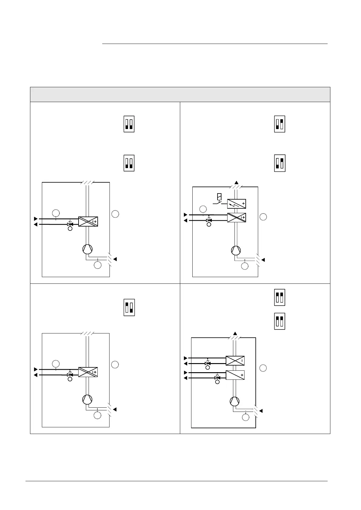
The controller supports following applications, which can be configured by DIP
switches on the inner side of the controller front panel. Depending on the type,
on/off or modulating control outputs are available.
Applications for fan coil systems
Application and output signal, DIP switches, diagram
· 2-pipe fan coil unit
ON/OFF
(heating or cooling)
ON
1 2
RDF300...
RDF400...
RDF600...
· 2-pipe fan coil unit
ON/OFF
(heating or cooling)
with electrical heater
ON
1 2
RDF300...
RDF400...
RDF600...
· 2-pipe fan coil unit
modulating, DC 0…10 V
(heating or cooling)
ON
1 2
RDF340
· 2-pipe fan coil unit
modulating, DC 0…10 V
(heating or cooling)
with electrical heater
ON
1 2
RDF340
3076D20
(B1)
M1
V1
T
B2
T
T
(B1)
V1
M1
3171D21
T
B2
E1
T
(B1)
T
(B1)
· 2-pipe fan coil unit
modulating, 3-position
(heating or cooling)
ON
1 2
RDF300...
RDF400...
RDF600...
· 4-pipe fan coil unit
ON/OFF
(heating and cooling)
ON
1 2
RDF300...
RDF400...
RDF600...
ON
1 2
RDF340
3076D 20
(B1)
M1
V1
T
B2
T
T
(B1)
T
V2
V1
M1
3076D22
(B1)
T
(B1)
V1 Heating or heating/cooling valve actuator M1 3-speed or single-speed fan
V2 Cooling valve actuator B1 Return air temperature sensor or
external room temperature sensor (optional)
E1 Electrical heater B2 Changeover sensor (optional)
 Loading...